8mm Forum


my profile | my password | search | faq | register | forum home
  next oldest topic   next newest topic
» 8mm Forum   » 8mm Forum   » GS1200 Blower Motor Connections (Page 2)

 - UBBFriend: Email this page to someone!  
This topic comprises 2 pages: 1  2 
 
Author Topic: GS1200 Blower Motor Connections
Thomas Knappstein
Expert Film Handler

Posts: 124
From: Erwitte, Germany
Registered: Oct 2017


 - posted October 06, 2019 02:02 AM      Profile for Thomas Knappstein   Email Thomas Knappstein   Send New Private Message       Edit/Delete Post 
It is not a special GS 1200 repair Group Paul. It is for repairing 8 and 16mm machines at all. There are many People who know what they did. And it is easier to load up some pictures.

 |  IP: Logged

Paul Adsett
Film God

Posts: 5003
From: USA
Registered: Jun 2003


 - posted October 14, 2019 02:16 PM      Profile for Paul Adsett     Send New Private Message       Edit/Delete Post 
The big transistor checked out ok. I got the new large Matsushita relay installed on the board as well as new 1B2C1 and 1B2Z1 rectifiers. I also replaced the motor governor board. The projector is now fully functional in all modes, and the original problem with the take up not working is now gone.
I still have one thing to do and that is to find an inductor coil for the blower motor, since the original has broken off and there is no way to solder it back on as there is no wire sticking out from it. For now I have just cut it out and reconnected the wire directly from the relay board to the motor. Consequently I can hear some RF interference from the fan motor on the sound. I am trying to find a suitable substitute inductor. Any suggestions much appreciated.

Needless to say I am delighted to get this wonderful projector fully functional again, and I cannot thank Phil, Thomas, and Leon, enough for helping me through this complex repair process.
When I first switched the machine on after all the repair work, I had no idea what to expect, but my reaction was something like this: [Big Grin]

https://www.youtube.com/watch?v=QuoKNZjr8_U

--------------------
The best of all worlds- 8mm, super 8mm, 9.5mm, and HD Digital Projection,
Elmo GS1200 f1.0 2-blade
Eumig S938 Stereo f1.0 Ektar
Panasonic PT-AE4000U digital pj

 |  IP: Logged

Thomas Knappstein
Expert Film Handler

Posts: 124
From: Erwitte, Germany
Registered: Oct 2017


 - posted October 14, 2019 10:31 PM      Profile for Thomas Knappstein   Email Thomas Knappstein   Send New Private Message       Edit/Delete Post 
Hi Paul!
Solder two 100nF Caps from the + and the- to the Motor Housing Ground. Than you can throw the green Coils both away and solder the Wires directly on the Brushes. I have done this on a machine, where the same Problem was. Works fine. No Noise in Speakers.

 |  IP: Logged

Paul Adsett
Film God

Posts: 5003
From: USA
Registered: Jun 2003


 - posted October 14, 2019 11:27 PM      Profile for Paul Adsett     Send New Private Message       Edit/Delete Post 
Thanks Thomas,but I am uncertain about the capacitance symbols you have used. Is that 100 micro farads?

--------------------
The best of all worlds- 8mm, super 8mm, 9.5mm, and HD Digital Projection,
Elmo GS1200 f1.0 2-blade
Eumig S938 Stereo f1.0 Ektar
Panasonic PT-AE4000U digital pj

 |  IP: Logged

Phil Murat
Jedi Master Film Handler

Posts: 671
From: Villeneuve St Georges, France
Registered: Dec 2015


 - posted October 15, 2019 01:07 AM      Profile for Phil Murat   Email Phil Murat   Send New Private Message       Edit/Delete Post 
Hi Paul,

Thanks for your comments and happy you get your machine back to work, "Congratulations" [Wink] !!!.

It is normal you observe "noises" in sound as 35V used for fan motor is common with 35 V comming to Amplifier.

Concerning "green" inductors , this system is more efficient than a capacitors system because inductors work as a plug and is designed to cut a specific noise Frequency Band.

A capacitors system is supposed to work too but instead to work as a plug it works like (more or less) as a short cut and not for a specific frequency.
In case a capacitor fails , it will probably short cut circuit, damaging last transistor (Fan motor feeder).

However, "Inductors" are 100% fail safe !!

Frequency of the noise depends on Motor Speed X Number of inner copper collectors.

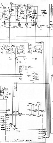
In reference to the schema posted above in this TIP , you need 3 unpolarized capacitors (propylen) to replace the dual inductances system :
- 1 Capacitor 470nf (Nano Farad)
- 2 Capacitors 47nf (Nano Farad)

Anyway, as it is highly recommended to keep this inductors system as noise suppressor, the good new is that an inductor can be done by yourself , like a copy of the original , knowing diameter of wire, diameter of core, total lengh , and keeping ferrite core.

[ October 15, 2019, 04:19 AM: Message edited by: Phil Murat ]

 |  IP: Logged

Paul Adsett
Film God

Posts: 5003
From: USA
Registered: Jun 2003


 - posted October 15, 2019 09:38 AM      Profile for Paul Adsett     Send New Private Message       Edit/Delete Post 
I'm wondering if there is anyway to determine the microhenry value of these inductors and how much fan motor current they should take. They don't seem to be identified in the GS1200 service manual, just part of the fan motor.
Any opinion on whether any of these inductors would work:

http://www.surplussales.com/Inductors/Chokes/Ind-MoldRFChoke.html

--------------------
The best of all worlds- 8mm, super 8mm, 9.5mm, and HD Digital Projection,
Elmo GS1200 f1.0 2-blade
Eumig S938 Stereo f1.0 Ektar
Panasonic PT-AE4000U digital pj

 |  IP: Logged

Phil Murat
Jedi Master Film Handler

Posts: 671
From: Villeneuve St Georges, France
Registered: Dec 2015


 - posted October 15, 2019 10:12 AM      Profile for Phil Murat   Email Phil Murat   Send New Private Message       Edit/Delete Post 
Hi Paul,

Not tested yet but I have just found that :

http://users.telenet.be/h-consult/Txradio/selfBerekening.htm

This is a little program in direct use.

Calculated value is (more or less) theoretic, because a same inductor will offer a fluctuating value depending on current fluctuation (this is the case because Fan motor has 2 different speeds)......
Generaly , at the end, the best way is to plug an oscilloscope and to determine if signal recorded is satisfactory.
Anyway when you don't ear anymore noise, game is won [Wink]

Concerning current crossing inductors , take a safety margin :
If Fan Motor power is around 30W-40W, voltage is 35V , stable current is around 1 to 2 Amps [Roll Eyes]

Frequency value to cut : using your ears you can determine an approximative value of the noise .You can Try 1000 HZ for exemple

An other one site but in French language (not tested) :

http://www.tavernier-c.com/bobinages.htm

It seems the usual name in English language for this inductor typical use is "Choke Coil" (To be confirm)

To give an other idea, an other product exemple, may be very closed, with detailed datasheet :

http://www.yfbalun.com/English/productshow_199.html

or

http://www.yfbalun.com/English/products_t29.html

[ October 16, 2019, 07:02 AM: Message edited by: Phil Murat ]

 |  IP: Logged

Thomas Knappstein
Expert Film Handler

Posts: 124
From: Erwitte, Germany
Registered: Oct 2017


 - posted October 16, 2019 08:42 AM      Profile for Thomas Knappstein   Email Thomas Knappstein   Send New Private Message       Edit/Delete Post 
Hi Phil!

The 35V for the Fan Motor are not the same a for the Amplifier. there is a seperate Coil on the Transformer and a seperate Rectifier with Cap for the Amplifier. With only two 100nF Capacitors it work as good as with the green Coils.

 |  IP: Logged

Phil Murat
Jedi Master Film Handler

Posts: 671
From: Villeneuve St Georges, France
Registered: Dec 2015


 - posted October 16, 2019 09:34 AM      Profile for Phil Murat   Email Phil Murat   Send New Private Message       Edit/Delete Post 
Hi Thomas,

In accordance with Elmo "wiring Diagram" (PDF P95/98) here below, I can see common 35V for "Fan Motor" and "Power Amp" :

 -

However, may be I have missed something.

The filtering solution (3 caps) I have suggested to Paul is often used by people using models scale radio controled.

[ October 16, 2019, 10:41 AM: Message edited by: Phil Murat ]

 |  IP: Logged

Thomas Knappstein
Expert Film Handler

Posts: 124
From: Erwitte, Germany
Registered: Oct 2017


 - posted October 16, 2019 10:47 PM      Profile for Thomas Knappstein   Email Thomas Knappstein   Send New Private Message       Edit/Delete Post 
Hi Phil!
This is only a piece of the whole Diagramm you have posted.
On the right Side of your Picture are the three caps with their rectifiers. And there you can see that the Amplifier has a seperate rectifier with Cap 4700µF/50V and two Toshiba Rectifiers.

 |  IP: Logged

Phil Murat
Jedi Master Film Handler

Posts: 671
From: Villeneuve St Georges, France
Registered: Dec 2015


 - posted October 17, 2019 02:21 AM      Profile for Phil Murat   Email Phil Murat   Send New Private Message       Edit/Delete Post 
Hi Thomas,

You're right,and this is exactly what I wrote (page 1 of this Topic, 14th post).
In summary, Amp section (Power Amp + Pre Amp, to be confirm) is powered by 2 seperates 35V bus and a 12v bus too.

 |  IP: Logged

Thomas Knappstein
Expert Film Handler

Posts: 124
From: Erwitte, Germany
Registered: Oct 2017


 - posted October 18, 2019 09:06 AM      Profile for Thomas Knappstein   Email Thomas Knappstein   Send New Private Message       Edit/Delete Post 
Hi Phil!

Yes you are right Excuse me.

 |  IP: Logged

Phil Murat
Jedi Master Film Handler

Posts: 671
From: Villeneuve St Georges, France
Registered: Dec 2015


 - posted October 19, 2019 12:03 AM      Profile for Phil Murat   Email Phil Murat   Send New Private Message       Edit/Delete Post 
Hi Thomas,

No Problem, anyway GS1200 shows sophisticated and complex systems.

 |  IP: Logged

Paul Adsett
Film God

Posts: 5003
From: USA
Registered: Jun 2003


 - posted October 19, 2019 10:45 AM      Profile for Paul Adsett     Send New Private Message       Edit/Delete Post 
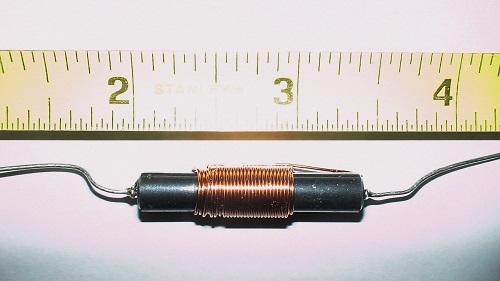
Well I went down to Radio Shack and picked up this 100 microhenry RF choke. I covered it with a tube of heat shrink and spliced it into the (broken) fan motor lead wire. I then switched on the projector, turned the lamp on so the fan was running at full speed, plugged in the earphones, and low and behold Zero EMI from the fan motor. This choked totally killed the noise. Stereo sound is now faultless. No doubt this particular choke is overkill, but it does the job, and there is plenty of room to solder it in by the motor.
Ain't science wonderful! [Smile]

 -

--------------------
The best of all worlds- 8mm, super 8mm, 9.5mm, and HD Digital Projection,
Elmo GS1200 f1.0 2-blade
Eumig S938 Stereo f1.0 Ektar
Panasonic PT-AE4000U digital pj

 |  IP: Logged

Phil Murat
Jedi Master Film Handler

Posts: 671
From: Villeneuve St Georges, France
Registered: Dec 2015


 - posted October 19, 2019 11:28 PM      Profile for Phil Murat   Email Phil Murat   Send New Private Message       Edit/Delete Post 
Hi Paul,

Great, you killed "noise" by a single shot, congratulations !!!

Coil wire section looks to be around 0,7 or 0,8mm, is it correct ?

N.B
Assume Doug will move this Topic in GS1200 room.

 |  IP: Logged

Paul Adsett
Film God

Posts: 5003
From: USA
Registered: Jun 2003


 - posted October 20, 2019 10:51 PM      Profile for Paul Adsett     Send New Private Message       Edit/Delete Post 
Phil, I have opened up a Technical topic named GS1200 FAN MOTOR INDUCTORS and link to this section so Doug can add it to the Technical Index.

--------------------
The best of all worlds- 8mm, super 8mm, 9.5mm, and HD Digital Projection,
Elmo GS1200 f1.0 2-blade
Eumig S938 Stereo f1.0 Ektar
Panasonic PT-AE4000U digital pj

 |  IP: Logged


All times are Central
This topic comprises 2 pages: 1  2 
 
   Close Topic    Move Topic    Delete Topic    next oldest topic   next newest topic
 - Printer-friendly view of this topic
Hop To:

Visit www.film-tech.com for free equipment manual downloads. Copyright 2003-2019 Film-Tech Cinema Systems LLC

Powered by Infopop Corporation
UBB.classicTM 6.3.1.2