8mm Forum


my profile | my password | search | faq | register | forum home
  next oldest topic   next newest topic
» 8mm Forum   » 8mm Forum   » Sankyo sound 600 motor problems repair (Page 0)

 - UBBFriend: Email this page to someone!  
This topic comprises 2 pages: 1  2 
 
Author Topic: Sankyo sound 600 motor problems repair
Phil Murat
Jedi Master Film Handler

Posts: 671
From: Villeneuve St Georges, France
Registered: Dec 2015


 - posted October 02, 2016 01:01 AM      Profile for Phil Murat   Email Phil Murat   Send New Private Message       Edit/Delete Post 
Hello Janice,

A) There is a high probability original TR Power is in good condition.

The breakdown design T° is around 150 °C , if you feel casing "extremly" hot, means T° is around 70°C. This is a bit too much and needs to be pull down.

B) I am not surprised considering T1 condition. If you find a capacitor fitted next to TR1 , it could be profitable to replace it (a faulty capacitor could be the "hiden" issue)

C) 5v or 6V are just the "breakdown" limit for these Power TR Base.
Normal operating voltage when regulating is around 0,6v for our case.

The Max Voltage limit is around 50V : You can measure Voltage "going in" from Big Capacitor Pins (1000 µf / 50V).

NTE152 looks a bit stronger, However , once installed, the 18/24 Adustable Resistors could need to be trim again.

IMPORTANT:
Some "vintage" TR are difficult to find and can be replaced by an "Equivalent" item. if overall limits are the same, however "response" curves could be different.
I have experienced this situation as I faced a similar failure for a BEAULIEU : I had to reinstall the same TR reference because régulation wasn't responding correctly.....

For exemple : If installing NTE152 makes the motor running to High (for any 18/24 setting) , you could be induced to compensate by adding a small resistor (may be 10 K) just before PIN 1.
As a primary experience, if original TR works properly, I suggest to keep it.

Let us know

[ October 02, 2016, 04:33 AM: Message edited by: Phil Murat ]

 |  IP: Logged

Janice Glesser
Film Goddess

Posts: 3468
From: Sunnyvale, CA USA
Registered: Sep 2011


 - posted October 02, 2016 08:05 PM      Profile for Janice Glesser     Send New Private Message       Edit/Delete Post 
Phil:

quote:
B) I am not surprised considering T1 condition. If you find a capacitor fitted next to TR1 , it could be profitable to replace it (a faulty capacitor could be the "hiden" issue)
There is a small capacitor (C2) 470uf 6.3V. I measured its capacitance in circuit and it appears to be good.

 -

I think I'm going to have to wait for the delivery of the new pots and the small transistors. I have a replacement for the big cap (C1)...but not for the small one (C2). So far T1 is the only component to appear defective comparing measurements to the working PCB. I don't know how to test the pots.

Because of the way the PCB is mounted on the heatsink and the high temperature... it's not legistically feasible and somewhat dangerous to measure voltage with the power plugged in.

--------------------
Janice

"I'm having a very good day!"
Richard Dreyfuss - Let It Ride (1989).

 |  IP: Logged

Phil Murat
Jedi Master Film Handler

Posts: 671
From: Villeneuve St Georges, France
Registered: Dec 2015


 - posted October 03, 2016 02:08 AM      Profile for Phil Murat   Email Phil Murat   Send New Private Message       Edit/Delete Post 
Hi Janice,

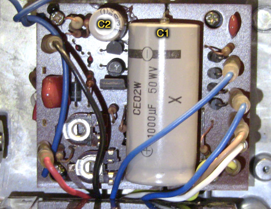
Due to this new picture I can see an other "small" TR (TR3, "half moon" shape) very next to C2 too. It probably works with T1 and T2, so, normally the thinking is identical for this TR.

C2: If 6,3 V is not available , you can choose 10 , 16, or 25v as well, it doesn't matter. (You just need "room" enough to fit it properly)

"New Generation" Capacitors are smaller than old ones for same value, so you can upgrade to a higher Voltage Limit at your conveniance.

POTs : Probability both pots to fail together and in a same time is very low.....

[ October 03, 2016, 04:20 AM: Message edited by: Phil Murat ]

 |  IP: Logged

Janice Glesser
Film Goddess

Posts: 3468
From: Sunnyvale, CA USA
Registered: Sep 2011


 - posted October 03, 2016 06:19 PM      Profile for Janice Glesser     Send New Private Message       Edit/Delete Post 
Yes Phil...there is another component lurking behind T1 [Smile] Turns out this is a Silicon Controlled Rectifier (SCR). The label says FOR2B. It's a TO-92 package. I'm having a tough time cross referencing this SCR to find an equivalent.

[ October 03, 2016, 10:08 PM: Message edited by: Janice Glesser ]

--------------------
Janice

"I'm having a very good day!"
Richard Dreyfuss - Let It Ride (1989).

 |  IP: Logged

Phil Murat
Jedi Master Film Handler

Posts: 671
From: Villeneuve St Georges, France
Registered: Dec 2015


 - posted October 03, 2016 11:58 PM      Profile for Phil Murat   Email Phil Murat   Send New Private Message       Edit/Delete Post 
Hi Janice,

Have a look for that :

High probability this standard Ref will suit you

SCR Design

May it helps you for testing this small Thyristor (This is a Diode driven by a Trigger "G Pin")

How to test a Thyristor ?
This is in French, but hope helps you too :

THYRISTOR

/////// To Be Confirm ///////////

Not sure, but it's possible this Thyr works with C2 as a circuit dedicated to TR1/TR2 protection against curent generated by motor during shutdown (Also call "Free Wheel" protection).
If this is the case, this area has to be in good condition.

[ October 04, 2016, 12:03 PM: Message edited by: Phil Murat ]

 |  IP: Logged

Mark Creighton
Junior
Posts: 21
From: Schodack, NY, USA
Registered: Mar 2016


 - posted October 04, 2016 11:50 AM      Profile for Mark Creighton   Email Mark Creighton   Send New Private Message       Edit/Delete Post 
Janice,

It appears that a NTE5402 might be a replacement for the FOR2B.
See
web page

 |  IP: Logged

Janice Glesser
Film Goddess

Posts: 3468
From: Sunnyvale, CA USA
Registered: Sep 2011


 - posted October 04, 2016 12:35 PM      Profile for Janice Glesser     Send New Private Message       Edit/Delete Post 
Thank you Mark very much. That's it! I'm thinking the transistor in front of the SCR is probably bad. I'm waiting on a replacement for it. Once that component is swapped out...then I can see if the SCR is still good. At least now I'll know the part to order if needed.

--------------------
Janice

"I'm having a very good day!"
Richard Dreyfuss - Let It Ride (1989).

 |  IP: Logged

Mark Creighton
Junior
Posts: 21
From: Schodack, NY, USA
Registered: Mar 2016


 - posted October 04, 2016 01:10 PM      Profile for Mark Creighton   Email Mark Creighton   Send New Private Message       Edit/Delete Post 
Janice,

There is a series SCR's in this configuration with different voltage ratings. They are NTE5400 through NTE5406.
NTE5400 30V
NTE5401 60V
NTE5402 100V
NTE5403 150V
NTE5404 200V
NTE5405 400V
NTE5406 600V

The other specs are identical, so you might want to use a NTE5403 or NTE5404.

Here is a link to the spec sheet NTE Spec Sheet

 |  IP: Logged

Janice Glesser
Film Goddess

Posts: 3468
From: Sunnyvale, CA USA
Registered: Sep 2011


 - posted October 08, 2016 11:12 PM      Profile for Janice Glesser     Send New Private Message       Edit/Delete Post 
Thanks Mark for the heads up on the voltages. Looks like I will be buying one.

I've been a little pre-occupied watching the baseball playoffs...but today I replaced the T1 transistor and the big C1 capacitor. I was hoping this would solve the problem...but no go [Frown] . At least I didn't blow anything up... everything ran fine ... except still can't adjust the speed.
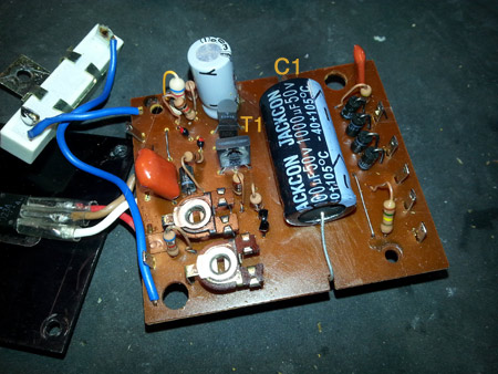
 -

Next I'll replace the SCR..C2 and T2. I haven't received the new pots yet.

--------------------
Janice

"I'm having a very good day!"
Richard Dreyfuss - Let It Ride (1989).

 |  IP: Logged

Janice Glesser
Film Goddess

Posts: 3468
From: Sunnyvale, CA USA
Registered: Sep 2011


 - posted October 09, 2016 03:28 PM      Profile for Janice Glesser     Send New Private Message       Edit/Delete Post 
UPDATE....Not good news [Frown]

Lack of experience has created a down-turn to this project. In replacing the T2 transistor I ran across the problem of the pins on the new transistor were wider than the holes in the circuit board. I decided to lightly hammer a brad into the hole to widen it...NOT RECOMMENDED! I didn't realize until after I turned the board over that it had crack the board and most likely broke one or more traces. [Mad] After this fiasco the motor will not turn on now.
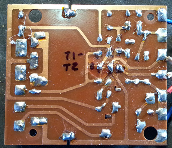
Probably the only hope for this projector is to find a working replacement board. I don't really feel up to trying to figure out what traces need repair.

But all is not lost in this scenario. I learned a ton about identifying and testing components. I specifically appreciate the assistance from Phil Murat. Phil you under estmate your knowledge and you troubleshooting skills. You definitely are not a beginner. I certainly am impressed as I'm sure others who have read any of this thread are also.

I'd also like to thank Mark Creighton for his input. I did order the SCR...unfortunately I won't be able to use it. What a shame...

Anybody have a speed board to a Sankyo 600 they want to sell?...Cheap [Wink]

--------------------
Janice

"I'm having a very good day!"
Richard Dreyfuss - Let It Ride (1989).

 |  IP: Logged

Phil Murat
Jedi Master Film Handler

Posts: 671
From: Villeneuve St Georges, France
Registered: Dec 2015


 - posted October 10, 2016 03:16 AM      Profile for Phil Murat   Email Phil Murat   Send New Private Message       Edit/Delete Post 
Hello Janice,

I understand you get problem with PCB material during T2 installation.
These former PCB's are fragile as this is not Epoxy Reinforced with Fiber matérial : It can crack easily and may be due to the age, tracks can stick out if overheated.

I met exactly these typical problems when working on my projectors.

So, don't be afraid too much, there is a high probability you can fix it anyway , making "Bridges" for the damaged tracks (small portion of wire and "Top off" concerned area with Tin).
As necessary, for exemple, pick up portion of wire from spare resistors.

Could you put here a picture for the Coper Tracks Side?

This is a precision work wich requires a magnifying lens (x3 approx) on stand.
Also I use a Headlamp (LEDLENSER are very good) and a precision soldering iron (narrow tip, 15W).
As necessary too, to extract Tin from tracks, you can use a Hand Depress Pump or Coper Mesh dependind on the configuration.

Standard Drills size for PCB holes are 0,8mm (sometimes 0,6mm for tiny components)

Remember also if T1 has failed it is important to find out the failure root. Otherwise installing a new one without solving the cause can lead it to fail again.

Courrage !!

NB:

Plan "B" :
In case nothing works and spare PCB hard to find, I think it is possible to "Clone" the former PCB.
That needs time but you can find a dedicated "Freeware" on the Web to carry out the drawing (professionnal result).
This is a simple lay PCB. Big advantage is you can get it in Epoxy material (more professionnal)for few USD.....

 |  IP: Logged

Andrew Woodcock
Film God

Posts: 7477
From: Manchester Uk
Registered: Aug 2012


 - posted October 10, 2016 03:58 AM      Profile for Andrew Woodcock         Edit/Delete Post 
Cloning the circuit boards sounds like a great idea Phil!

Maybe a few of our machines would benefit from having some spare boards.

Do you design them yourself using the freeware?

--------------------
"C'mon Baggy..Get with the beat"

 |  IP: Logged

Phil Murat
Jedi Master Film Handler

Posts: 671
From: Villeneuve St Georges, France
Registered: Dec 2015


 - posted October 10, 2016 04:29 AM      Profile for Phil Murat   Email Phil Murat   Send New Private Message       Edit/Delete Post 
Hi Andrew,

I have started to make a simple board for a small power card as a primary experience, as you kwow , I am still working on an Embeded "Frequencemeter" for my Beaulieu's :

2 devices (and their Infrared probes) are almost ready to install inside rear cover .

Now,I just need to pick up a little power from big transformer inside Beaulieu 708(I mean Lamp Coil) and to adapt voltage to Frequencemeter (Power consumption estimated is 0,3 A, approx)..... [Wink]

However the "first juice" for my PCB power is not very good looking, right now, because I met problem during printing drawing on the PCB
[Roll Eyes]

To follow

 |  IP: Logged

Andrew Woodcock
Film God

Posts: 7477
From: Manchester Uk
Registered: Aug 2012


 - posted October 10, 2016 04:38 AM      Profile for Andrew Woodcock         Edit/Delete Post 
Let us know of your progress please Phil. This is exciting work here and the results will be amazing I'm sure! [Wink]

--------------------
"C'mon Baggy..Get with the beat"

 |  IP: Logged

Janice Glesser
Film Goddess

Posts: 3468
From: Sunnyvale, CA USA
Registered: Sep 2011


 - posted October 10, 2016 06:59 PM      Profile for Janice Glesser     Send New Private Message       Edit/Delete Post 
Hi Phil...your words have inspired me to move on with trying to repair this board. I admit to being very discouraged for about a day... but you have opened my eyes to alternatives. The idea of repairing or bridging the bad traces...or possibly creating a completely new circuit board all sound doable and something new to learn.

Here is a pic of the traces side of the PCB. The damaged areas are to the right of where I've labeled T1-T2.

 -

[ October 10, 2016, 08:12 PM: Message edited by: Janice Glesser ]

--------------------
Janice

"I'm having a very good day!"
Richard Dreyfuss - Let It Ride (1989).

 |  IP: Logged

Phil Murat
Jedi Master Film Handler

Posts: 671
From: Villeneuve St Georges, France
Registered: Dec 2015


 - posted October 11, 2016 02:07 AM      Profile for Phil Murat   Email Phil Murat   Send New Private Message       Edit/Delete Post 
Hello Janice,

At first sight, the tracks overall condition looks OK. There are minor damages, anyway bridges are properly done.

Observing PCB through side tracks is helpful to anticipate complementary checks for other components :

Could you check what happens when the "white bloc" fitted on steel bracket (and blue wired) is disconnected from PCB)?

-Observe effect as speed motor change for exemple.
If speed decrease, check "Pots" for efficiency.

-There is a high probability this is a Interference-Suppression Capacitor , however do not let motor running a long time when capacitor disconnected.

Let us know....

Moreother, a good news is this circuit is not too much sophisticated.

If you like attempting a "cloning" experience , try that (This is in French language , but quite a "basic" use anyway) :

TCI DOWNLOAD FREEWARE

This is a "Lightweight" software (331ko). "Framework" Microsoft installation is prerequisite.

TCI.exe is compacted. Upon first time lauching it expenses in different files. The total size is around 1 MO once expended !!

Have a great fun !

As a first Test , making any drawing you want, you can select the drawing with the mouse, make "Copy" (Rh "Clic" if I remember)

and Paste in a "Word" page (for exemple). After that, Change picture from "Red" Color to Dark Black 100%, adjust the picture size to get the truth size (as a try and test procedure).....this is almost ready to transfer on a PCB !!!

[ October 11, 2016, 09:16 AM: Message edited by: Phil Murat ]

 |  IP: Logged

Mark Creighton
Junior
Posts: 21
From: Schodack, NY, USA
Registered: Mar 2016


 - posted October 11, 2016 01:21 PM      Profile for Mark Creighton   Email Mark Creighton   Send New Private Message       Edit/Delete Post 
Janice,

I found this video from MIT on creating a circuit board from a photo copy. MIT

They also make copper circuit boards that are photo sensitive to do the same thing.

Good luck with the repair.

 |  IP: Logged

Paul Browning
Phenomenal Film Handler

Posts: 1006
From: West Midlands United Kingdom
Registered: Aug 2011


 - posted October 11, 2016 01:48 PM      Profile for Paul Browning   Email Paul Browning   Send New Private Message       Edit/Delete Post 
Janice, I have had boards completely blow the track off and leave no trace. So get your magnifier first, and have a good look at the tracks, they are very thin just a few thousandths of an inch thick, easily destroying if stray mains goes down one when it should not be there. You can create PCB'S with a good digital camera and photo editing software( like paintshop pro)to change the colour lines to black and then print on clear a4 sheets for the old overhead projectors.

 |  IP: Logged

Janice Glesser
Film Goddess

Posts: 3468
From: Sunnyvale, CA USA
Registered: Sep 2011


 - posted October 11, 2016 04:31 PM      Profile for Janice Glesser     Send New Private Message       Edit/Delete Post 
Stop the presses!!! I can hardly contain my excitement [Smile] [Big Grin]

I fixed it!

When Phil said the damage didn't look that bad. I decided to try and repair the traces. After watching a couple videos on YouTube on repairing cracked circuit boards... I fired up my soldering iron and gave it a go.

There were 4 hairline breaks in the traces. I repaired those with some solder bridges. Now with the traces repaired I tested it again with the new T2 transistor installed...SUCCESS!!!! The motor started up and adjusting the pots raised and lowered the speed of the motor as well as the 18/24 selector switch on the front of the projector. It appears that the replacement NTE295 transistor was the last key to fixing the variable speed control.

I'm going to run it for a while to see that the power transistor doesn't get too hot and also run some test film to make sure it runs at the correct speeds.

[ October 11, 2016, 09:32 PM: Message edited by: Janice Glesser ]

--------------------
Janice

"I'm having a very good day!"
Richard Dreyfuss - Let It Ride (1989).

 |  IP: Logged

Andrew Woodcock
Film God

Posts: 7477
From: Manchester Uk
Registered: Aug 2012


 - posted October 11, 2016 11:47 PM      Profile for Andrew Woodcock         Edit/Delete Post 
Great news Janice!
It just goes to show that persistance and a "never say die" approach, really does pay off!
Very well done here and to those who assisted with similar machines. [Smile] [Wink]

--------------------
"C'mon Baggy..Get with the beat"

 |  IP: Logged

Phil Murat
Jedi Master Film Handler

Posts: 671
From: Villeneuve St Georges, France
Registered: Dec 2015


 - posted October 12, 2016 01:28 AM      Profile for Phil Murat   Email Phil Murat   Send New Private Message       Edit/Delete Post 
Hello Janice,

This is a Happy news !!!!!

"DOUBLE" CHAMPAGNE!!!

Troubleshooting is often time an "Exciting Game of Patience"

Very Good Job !!!, you are a chief (In France, we are also used to say "Respect" or "Chapeau")

There is a high probability the Power TR T° is right now much better , as current crossing it is properly calibrated now.

The Heatsink plate is offering a good size. Normally , T° around 40° is a reasonnable and acceptable estimation.......

Let us know !!

NB
In case in the future you need to work anymore "classical" PCB, check for the Iron power. 15w is enough for soldering tiny tracks and sensible components too. (associated to an Iron Narrow tip)
Moreover , remember : 5 seconds is the max time allowed for soldering many Electronic components without getting them to fail out.

If you are still interested in PCB "Reverse Engineering" take a look for that :

EASY EDA Tutorial

This is in English language and looks........very powerful

I have never used it , but, nothing to install or download, EASY EDA only works with any Web Navigator

[ October 12, 2016, 04:03 AM: Message edited by: Phil Murat ]

 |  IP: Logged

Steve Klare
Film Guy

Posts: 7016
From: Long Island, NY, USA
Registered: Jun 2003


 - posted October 12, 2016 06:06 AM      Profile for Steve Klare   Email Steve Klare   Send New Private Message       Edit/Delete Post 
I've been following this, but not chimed in because I don't know this machine.

If I had this problem I'd fake the damaged printed circuit board by building it up on vector board (because that's what I know).

That much being said, the next time I go to build something that I might have done using vector board, I'm going to look into making my own PCB instead! As long as the circuit wasn't going to need a lot of changes to work right, it would be much neater.

Nice job, all!

--------------------
All I ask is a wide screen and a projector to light her by...

 |  IP: Logged

Jase Serre
Junior
Posts: 1
From: Phoenix, AZ, USA
Registered: Jan 2017


 - posted January 25, 2017 09:01 AM      Profile for Jase Serre   Email Jase Serre   Send New Private Message       Edit/Delete Post 
Hi everyone...i am a new user here. As per my knowledge problem is an Electrolytic capacitors which had dried out and makes a short circuit. Considering age of the projector, and cheapness of this components, very easy to find too, don't try to test it and renew directly.If capacitor original voltage is not available, choose upper rate, just the Capacitor size increase.

low cost pcb assembly

[ April 19, 2017, 03:39 PM: Message edited by: Jase Serre ]

 |  IP: Logged

Andrew Woodcock
Film God

Posts: 7477
From: Manchester Uk
Registered: Aug 2012


 - posted January 25, 2017 05:00 PM      Profile for Andrew Woodcock         Edit/Delete Post 
New maybe Jase, spot on however, you are though!

--------------------
"C'mon Baggy..Get with the beat"

 |  IP: Logged

Manar El Harake
Junior
Posts: 2
From: Beirut, Lebanon
Registered: Apr 2019


 - posted April 11, 2019 07:57 AM      Profile for Manar El Harake     Send New Private Message       Edit/Delete Post 
My Sankyo Sound 600 was set to 110v and someone plugged it to 220v. it stopped working. any instructions for troubleshooting?

 |  IP: Logged


All times are Central
This topic comprises 2 pages: 1  2 
 
   Close Topic    Move Topic    Delete Topic    next oldest topic   next newest topic
 - Printer-friendly view of this topic
Hop To:

Visit www.film-tech.com for free equipment manual downloads. Copyright 2003-2019 Film-Tech Cinema Systems LLC

Powered by Infopop Corporation
UBB.classicTM 6.3.1.2