This is topic Repairing a Sankyo Stereo 800 - The Journey in forum 8mm Forum at 8mm Forum.
To visit this topic, use this URL:
https://8mmforum.film-tech.com/cgi-bin/ubb/ultimatebb.cgi?ubb=get_topic;f=1;t=008244
Posted by Janice Glesser (Member # 2758) on June 06, 2013, 02:34 PM:
I just bought a Sankyo Stereo 800 off Ebay that listed that it powered on but the lamp and spindles didn't turn. Well upon receiving it today the motor in fact does not power on... explaining why the spindles weren't turning ![[Frown]](frown.gif) I will most likely be returning it and trying to get a refund. However, before I do that... does anyone know how I can check to see if power is getting to the motor. When I plug it in a light goes on in the front and I hear a slight pop from the speaker...but that's about it.
I will most likely be returning it and trying to get a refund. However, before I do that... does anyone know how I can check to see if power is getting to the motor. When I plug it in a light goes on in the front and I hear a slight pop from the speaker...but that's about it.
Posted by Steve Klare (Member # 12) on June 06, 2013, 05:57 PM:
Hi Janice,
The best way I can think of is to hang a voltmeter on the motor's terminals (assuming you can get access).
If you aren't sure which it is you'd need to measure both AC and DC.
Posted by Maurizio Di Cintio (Member # 144) on June 06, 2013, 07:22 PM:
The motor on the Sankyo Stereo 800 is powered by DC, being electronically controlled.
From what you say, Janice, it could be a motor failure or a failure in the electronic board which controls the motor. Do you get any hum from the speakers with the volume knobs turned all the way clockwise? If so, the transformer is working but for some reason the current isn't getting to the motor or the motor might be broken/in need of maintenance (dirt removal, worn-out brushes etc).
As for the lamp, excluding it blew, it might depend on dirty/oxidized lamp terminals, or the connector might be dirty/oxidized; try cleaning both with some contact cleaner and 'energic' rubbing (once I had to use the finest sandpaper to clean the lamp terminals, but eventually the lamp lit...)
Perhaps you might re-sell it for parts or sell individual parts after disassembling them. Also the lens might be worth something especially if it's the "PRO ZOOM 1.0" which is quite rare.
Posted by Janice Glesser (Member # 2758) on June 06, 2013, 08:30 PM:
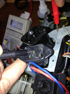
Thanks Steve...but I'm quite the spaz with the voltmeter. Other than checking for continuity on a couple of things in the past...I don't have a clue to what I'm doing. There are a couple wires going into the motor at the top...but they are shielded and sealed...can't get to the wires.
I appreciate the info Maurizio. I did turn up the volume and yes there is hissing coming from the speaker. Also, the lamp wasn't working because it was burned out...put in a new bulb...and nice and bright. So as you said... power is getting to the transformer...just not the motor or maybe it's a problem with the circuit board.
I'm pretty bummed about this. It's a beautiful projector...one I've had my eye on for a long time. I thought this was my opportunity. I paid way too much money for it to keep it and sell for parts. I'm going to try and negotiate with the seller. If he hadn't stated that it "powers on" I wouldn't have made an offer.
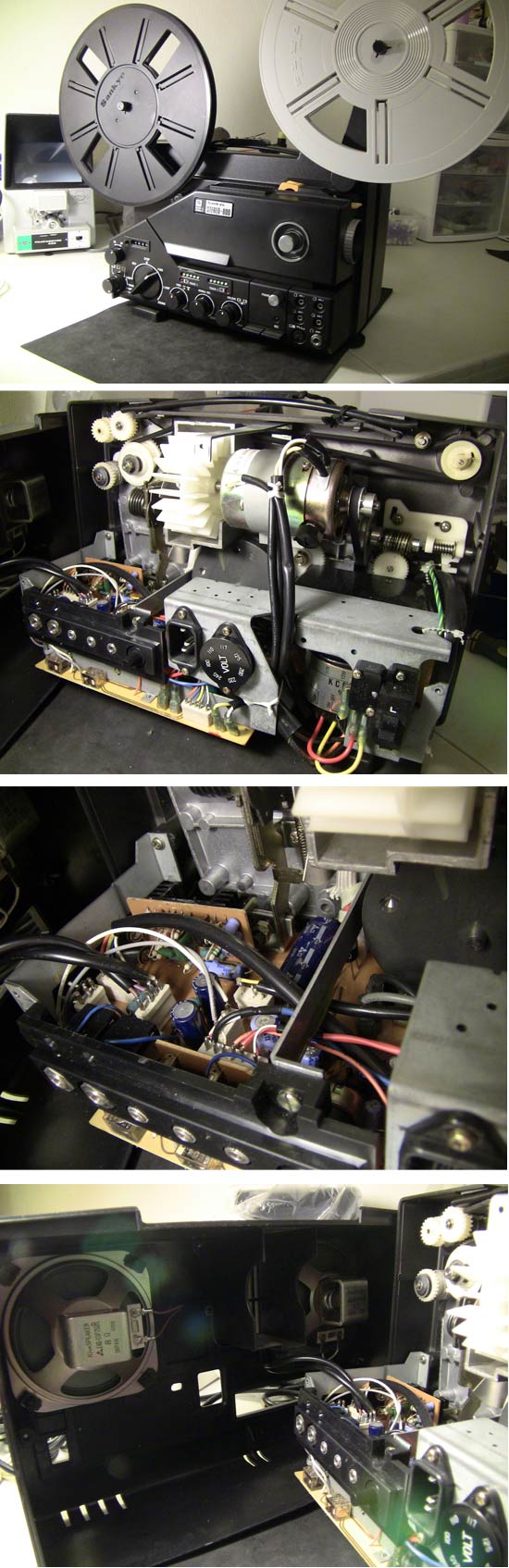
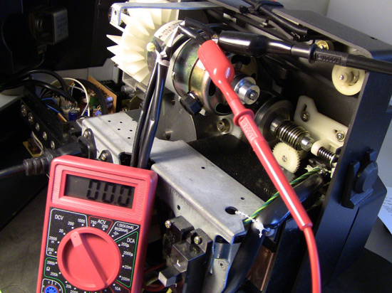
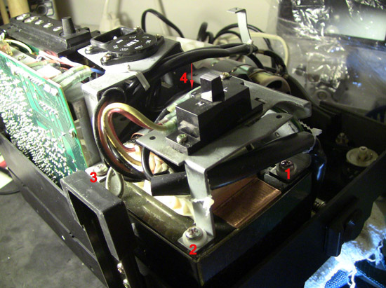
Here are a few pics I took. I really like Sankyo projectors.
Posted by Steve Klare (Member # 12) on June 07, 2013, 02:19 AM:
Janice,
Somebody with your skills really needs to learn how to use a multimeter: in situations like this one it can answer a lot of questions without making expensive guesses.
If you can somehow unplug the motor wires at the far end end measure the continuity between pairs that can tell you a lot. The fat pair is power. This should be very low in ohms. If it comes up in the thousands or millions of ohms the motor is DOA. The skinny pair is probably a motor speed sensor. Your motor speed is zero right now so let's find out if there is power in the first place.
-then again, sending the machine back and trying again some other day could be the best way to go too. You can't win them all!
Posted by Pasquale DAlessio (Member # 2052) on June 07, 2013, 02:26 AM:
Janice
Sometimes you can force the test probes from the voltmeter into the black insulated wires at the motor. They don't have to go very far in to make contact. Then test for voltage when the projector is turned on. Or you can make a very small slit in the black surrounding the wires at the motor to get a better connection. These motors are designed to last for years. I'm sure you can handle this. Go for it!
I agree with you about this projector. It's runs great and is not harmful to films at all.
PatD
Posted by Steve Klare (Member # 12) on June 07, 2013, 02:36 AM:
'Morning Pat!
I'd force sewing pins through the insulation, but only if I could clip leads onto them, make sure nothing live is touching surfaces they shouldn't and stand back.
Pressing test probes on with your finger tips is no way to figure out it's really a 117V circuit!
The machine is very clean inside: looks like it hasn't got a lot of miles on it!
Posted by James N. Savage 3 (Member # 83) on June 07, 2013, 05:17 AM:
Hi Janice-
I own a Sankyo ST-800 too and its a very good machine! The one you have there looks to be in very good condition and I wouldn't be surprised if the problem is just something very simple. I really wish I was more knowledgable about electronics and could give a better educated answer, but I usually fix projectors by "tinkering" until it works ![[Wink]](wink.gif) .
.
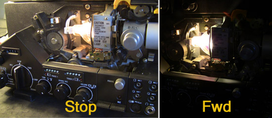
The problem sounds like it might just be with the switch. Did you try forward and reverse? Does the bulb stay in warm-up mode (dim) until you turn the switch to forward (two clicks) and then bright?
James.
Posted by Maurizio Di Cintio (Member # 144) on June 07, 2013, 06:36 AM:
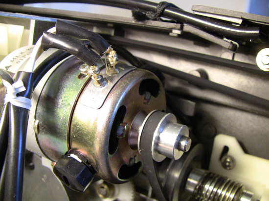
Janice, just pull the two black protection at the end of the larger wires on the motor: this will uncover the soldering points and there you can measure with a voltmeter/tester.
I agree with others the machine seems to have seen very little use. Do not be afraid of the electrics going into the motor: it's direct current at 12-15 V, really harmless, considering the skills you proved in other posts of yours. Do not quit. I have the schematics for this specific model, let me have your email and I'll post some scans of the motor control board as soon as I find some moments to do it.
Posted by John Capazzo (Member # 157) on June 07, 2013, 06:45 AM:
This isn't the first time I've heard of motors failing on Sankyo machines. It's VERY rare for Elmo motors to fail, but Sankyo machines are almost common.
Posted by Janice Glesser (Member # 2758) on June 07, 2013, 08:40 AM:
OK guys...I'll give it a go. Right now I wish my litte multimeter was made by Fisher-Price...with buttons that talked and lights that blinked when you selected the correct measurement ![[Big Grin]](biggrin.gif)
If you can bear with my learning curve...can you guide me through the first test?
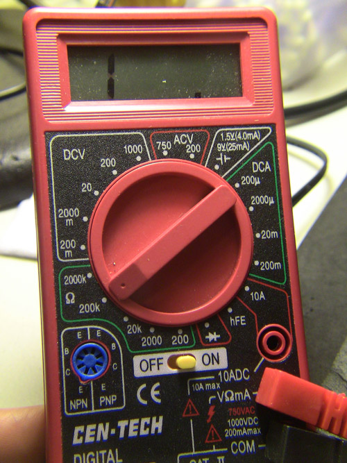
1. First tell me where the dial should be positioned on my multimeter.
2. Next, I know the Black probe is always placed in the common...but I'm not sure about the Red probe.
3. Now where do I place the probes (black probe goes ?...red probe goes ?) and what am I testing?
Is the machine plugged in for this particular test?
If you need more photos just let me know...that I can do ![[Smile]](smile.gif)
I was able to raise the heat shrink on the two motor wires..thanks for the tip Maurizio.
Posted by Steve Klare (Member # 12) on June 07, 2013, 09:11 AM:
Ok,
Here we go!
Machine plugged in, set mind on "careful!".
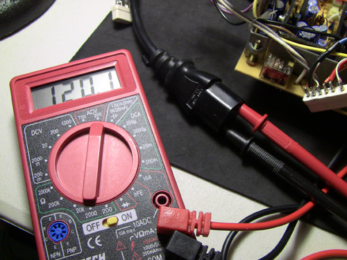
The meter dial goes to "200" in the section "DCV"
You take one lead and touch one terminal (and only the terminal!), take the other lead and touch it only to the other terminal. The only difference flipping them makes is one way the number will have a minus sign, the other it will not.
You should see zero(ish) when you expect the motor to be off. You should see something (12V, 20V, 24V?) when it's supposed to be on.
Best way to do it is carefully connecting up using leads with alligator clips or EZ hooks, but one way or the other be careful and respect that metal motor case! Shorting to it can cause grief you didn't start out with.
Posted by Patrick McGrath (Member # 1210) on June 07, 2013, 09:12 AM:
I repaired one of these with the same issue two years ago.
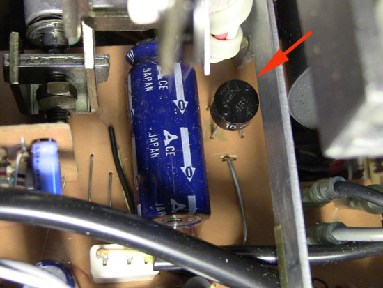
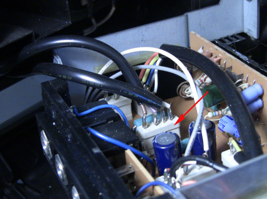
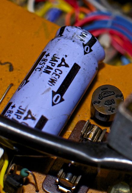
Check where the transformer leads run to the circuit board. At that point there is a small component called a bridge rectifier. It is small and round. Check to see if it is burned out. It will be obviously damaged.
By replacing that and the electrolytic capacitor(50v 1000uf)just after it, I managed to get my 800 up and running. 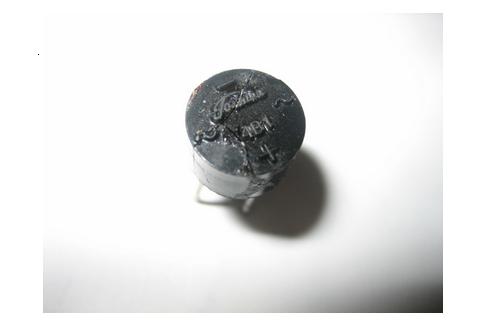
Posted by Steve Klare (Member # 12) on June 07, 2013, 09:31 AM:
Patrick,
Did this pop a fuse too?
Posted by Patrick McGrath (Member # 1210) on June 07, 2013, 10:22 AM:
I don't remember now but probably yes.
Posted by Steve Klare (Member # 12) on June 07, 2013, 10:53 AM:
It could go either way.
Unfortunately semiconductors often pop faster than the fuses that are supposed to protect them.
Janice, it's important to take the lamp out while you sort this out. Remember: no motor, no cooling air!
Posted by Janice Glesser (Member # 2758) on June 07, 2013, 12:41 PM:
Here's the results Steve:
Meter showed zero when switched to any on position (forward, reverse, lamp on, sound).
I think I located Patrick's. "Flux Capacitor"...OOOPS!... I mean Bridge Rectifier To my eye it doesn't appear damaged.
quote:
Does the bulb stay in warm-up mode (dim) until you turn the switch to forward (two clicks) and then bright?
Yes James...the switch is working correctly for the lamp.
You mention fuses Steve...Were you talking about house fuses or projector fuses? I didn't find any fuses in this machine. Are there any?
[ June 07, 2013, 01:55 PM: Message edited by: Janice Glesser ]
Posted by Steve Klare (Member # 12) on June 07, 2013, 02:36 PM:
Hi Janice,
It sounds to me like you are making some progress! I think your motor is not the problem.
I'm guessing Patrick's rectifier and capacitor are the power supply for your motor. Why not apply your newly aquired voltage measuring skills right on the two terminals of that capacitor?
I mean a fuse inside the machine. Our friends at Underwriters Laboratories insist that an appliance has a fuse or a circuit breaker so that when a short circuit develops inside, it doesn't (you know) burst into flames. If you see a "UL" on the serial number plate there is at least one fuse in there. (Never seen an 8mm projector with a breaker!)
(If Mrs. Murphy's Cow had a fuse, Chicago wouldn't have burned!)
Posted by Janice Glesser (Member # 2758) on June 07, 2013, 10:00 PM:
Well...I have bad news to report. Now I know I should stay out of the electrical arena. In attempting to attach the alligator clips to the rectifier which is in a very tight position...I had to remove one of the plastic covers from the clip to get it to fit. I put in the plug and the meter still read 0.00. The alligator clip slipped and hit a piece of metal...sparks flew and I heard a pop Im ok...but, I'm sure something in the sound blew...because now when I plug it in there's no popping sound and the track light is off ![[Mad]](mad.gif)
Thanks for all the help. At least there are some nice pictures posted that might help someone else. I'm going to try and return the projector and hopefully get my money back. I have a feeling that's not going to be easy either. The seller hasn't returned my email yet.
Posted by Steve Klare (Member # 12) on June 08, 2013, 06:41 AM:
Ouch!
Maybe you just blew a fuse!
I actually meant you should clip onto the capacitor (large blue part) next to the rectifier.
If yout did clip to the rectifier at the right point and saw zero, it means that there is a problem in the power supply circuit. This could be the transformer secondary, the lines (and fuse?) to the rectifier and or that capacitor.
Posted by Maurizio Di Cintio (Member # 144) on June 08, 2013, 08:44 AM:
Hi Guys! I had an issue with the rectifier myself years ago and from experience I have to say it is not obvious the rectifier looks damaged when become useless, in fact mine looked al right but wouldn't work. Replaced it and voilà everything started to work again.
Anyway, Janice I think the problem with your Sankyo is nothing an expert electrician cannot fix. Give me a couple of days and I'll let you have some scans with the schematics. OK?
Posted by Janice Glesser (Member # 2758) on June 08, 2013, 11:21 AM:
Sure Maurizo...Of course I won't understand the schematics though. I think my email is in my profile...but I'll PM it to you anyway. I have an electronic repair shop located very close to me. I could take it there to see if they could work on it.
Steve... At the early stage of my learning curve probably if you had called it the "The Big Blue Thingy" ...I would have known what you ment Oh Well...What's done is done. This projector is definitely worth fixing. I'm just not sure if I'll be able to orchestrate it.
Posted by Janice Glesser (Member # 2758) on June 12, 2013, 11:54 AM:
Well...looks like I'm keeping the projector. The seller finally responded after 5 days. He offered to refund half my money back. That amount still made this an expensive doorstop...but I accepted the offer. Maurizio was kind enough to send me the schematics. Perhaps I can find someone willing to work on it.
I never got around to checking that big blue thingy...although I don't want to burn anything else out in the process. I think I'm like a bull in a china shop when it comes to electricity
Thanks everyone for helping me out and if you know of someone who might be willing to fix it...please let me know.
Posted by Barry Fritz (Member # 1865) on June 12, 2013, 12:55 PM:
Doktor Frank, are you out there? There is a damsel in distress!
Posted by Pete Richards (Member # 2203) on June 12, 2013, 10:58 PM:
I can help you out once I get home this weekend. We can test some voltages at various points around the boards and find out where the problem is. I have a big list of expected voltages from when I repaired my one years ago.
Posted by Lee Mannering (Member # 728) on June 13, 2013, 03:41 AM:
Hi Janice. I had one of these way back when they were new and was problems from the start out of the box. Dry solder joints on the motor speed control circuit board and eventually the micro switches packed in which are located left and right behind the main control knob. I would start by changing the two micro switches you can see which is a fiddly job but my money would be on them and probably the one to the right.
Posted by Janice Glesser (Member # 2758) on June 13, 2013, 11:12 AM:
Thanks Lee for the advice...and Pete, I'm going out of town this weekend to visit family and celebrate Father's Day with my step dad. I'll be back on Monday. I will have my laptop with me..so if you post a test I should do...I'll do it when I get back.
[ June 15, 2013, 03:04 AM: Message edited by: Janice Glesser ]
Posted by Janice Glesser (Member # 2758) on June 17, 2013, 08:27 PM:
Pete...I'm back home now and ready to work on the projector. Were you going to guide me through some testing? I just want to make sure this time that I'm clear on the components I'm suppose to be testing:) I will probably verify by posting a photo. I also need to test to hopefully identify what blew out this last time.
Posted by Pete Richards (Member # 2203) on June 17, 2013, 10:58 PM:
I'll take a look at it tonight (Australia time) and write something up for you.
Cheers
-Peter
Posted by Janice Glesser (Member # 2758) on June 24, 2013, 03:08 PM:
Hi Pete...I PM'd you. When I blew out the sound on my last testing...could this have blown a fuse. I don't see any tube type fuses on this machine, but Steve says it has to have fuses. Where are they?
Posted by Pete Richards (Member # 2203) on June 24, 2013, 03:47 PM:
Sorry Janice, I haven't forgotten you, I unexpectedly ended up away from home until this morning.
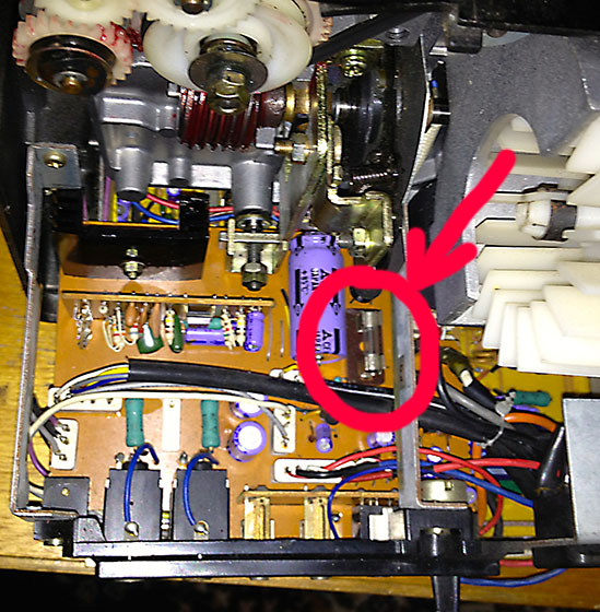
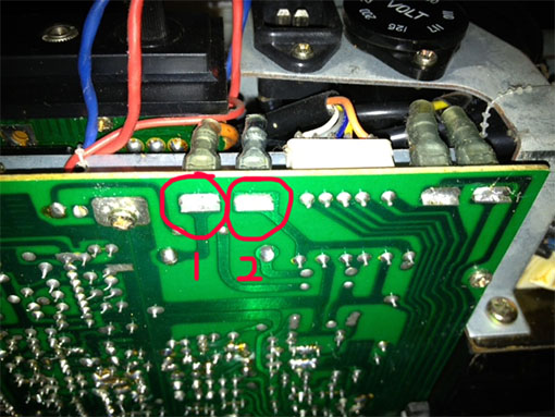
Circled in red is the fuse on that board, it is next to the huge capacitor. Make sure the projector has been turned off and disconnected from the power for a few hours at least to let the capacitors discharge so they don't zap you!
Posted by Janice Glesser (Member # 2758) on June 24, 2013, 06:50 PM:
Interesting Pete...Looks like Sankyo made some design changes on these machines. Take a look back at my photo posted on June 7th. No fuse...just a wire ![[Confused]](confused.gif) ...and your capacitor looks shorter to me.... but maybe not
...and your capacitor looks shorter to me.... but maybe not ![[Roll Eyes]](rolleyes.gif)
[ June 24, 2013, 10:37 PM: Message edited by: Janice Glesser ]
Posted by Pete Richards (Member # 2203) on June 24, 2013, 11:26 PM:
The capacitor is the same size. Someone may have replaced the fuse with a wire at some point. Not good!
I can get the meter out the day after tomorrow and record some test points for you to follow along with, I'll video it if I can.
Just remember to be careful, there is 220v kicking around!
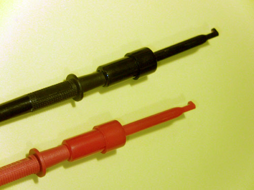
You might want to get a pair of multimeter leads with hooks on the end, like these
http://www.ebay.co.uk/itm/2-2-Long-Meter-Multimeter-Lead-Wire-Testing-Hooks-Clip-Blue-2-Pcs-/290913239550?pt=UK_BOI_Electrical_Test_Measurement_Equipment_ET&hash=item43bbc7c1fe
It makes it easier to avoid short circuits.
[ June 25, 2013, 12:37 AM: Message edited by: Pete Richards ]
Posted by Janice Glesser (Member # 2758) on June 25, 2013, 10:49 AM:
Great Pete...I'll see if I can pick up those hooked probes at Radio Shack today.
*Got them*... These are great...wish I had had these before...much safer. I WILL be careful though.
[ June 25, 2013, 02:11 PM: Message edited by: Janice Glesser ]
Posted by Janice Glesser (Member # 2758) on June 25, 2013, 02:53 PM:
I noticed Pete that you have the speaker wires disconnected in your photo. It would be nice to not have the back cover attached to give easier access to the components. Does the connector remove as one piece by just lifting it up? I don't want to mess with it unless I know more about how it's connected.
Posted by Pete Richards (Member # 2203) on June 25, 2013, 07:43 PM:
Yes, you can just unplug it.
Posted by Janice Glesser (Member # 2758) on July 02, 2013, 03:11 PM:
Frank Arnstein's comment from another thread:
quote:
I think there is a small hidden glass line-fuse inside the wiring loom, somewhere behind the power socket. Its covered in black plastic tubing so you will need to cut it out when you find it. Also check the motherboard visually for burnt out printed circuitry.
I'll look for the fuse Frank. I may have blown that with my failed testing incident.
I want to gather as much information before I take it to an electrician. I'm sure most haven't seen a film projector circuit board before
UPDATE: Frank other than the fuse location Pete shows in his photo, which is missing on my machine...I don't see another fuse anywhere...and nothing in the power socket area.
[ July 02, 2013, 06:44 PM: Message edited by: Janice Glesser ]
Posted by Pete Richards (Member # 2203) on July 03, 2013, 07:34 AM:
Just going over the projector now with the meter to follow the path of the power and come up with some test points for you. Sorry it has taken so long, I unexpectedly lost both Grandmothers within days of each other, it has been an up and down week.
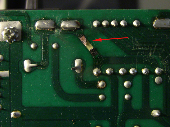
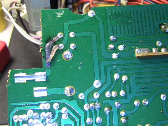
First thing to check is that power is getting to the main board. With the power cord *disconnected* open up the projector, and lay it down carefully so that the front is face down on the table. Check the bottom of the green PC board for any scorch marks or damage. If it is clean then attach your test probes to the bottom of the board where the 15V AC comes to the board. On mine the wires are Orange and black. Set your voltmeter to AC voltage (~) and if it is not autoranging, set it to above 200V in case there is a short.
Apply the power and the voltmeter should read approximately 15V AC. It doesn't matter which way around the probes are.
If that voltage isn't present, then either there is a hidden fuse, or the main transformer is burned out, or one of the wires has burned out. It is a good first place to check.
Posted by Janice Glesser (Member # 2758) on July 03, 2013, 12:15 PM:
This doesn't look good to me Pete...and no voltage reading. What do you think?
Posted by Akshay Nanjangud (Member # 2828) on July 03, 2013, 02:38 PM:
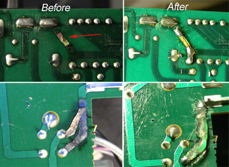
Janice, I had similar issues on my ST-1200 PCB ..... only worse. So I got a friend and we soldered wires where we felt the connections had corroded. Take a look at the image here: Link. I can reply with more details, if you want.
Posted by Pete Richards (Member # 2203) on July 03, 2013, 09:39 PM:
Well... I guess the good news is that we know one reason it isn't powering up!
Before soldering anything, put the test probes on the points I have circled and we can see if the 15V is getting to the board at all.
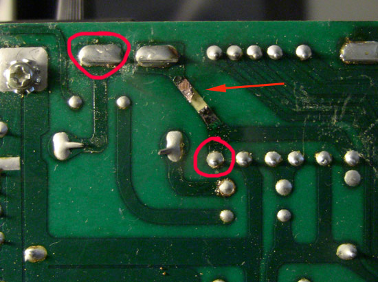
If those test points show 15V AC, then it is easy to solder a wire in place of the burned out PCB track. I'm 99sure that you will still have no voltage there though.
If no voltage is showing, then we need to physically trace the wire on the right-hand-side (the black one) and see where it goes and if there is a fuse hidden along it somewhere, or if the wire itself has burned out.
Posted by Brian Stearns (Member # 3792) on July 03, 2013, 10:14 PM:
What a nightmare, Its always a risk buying projectors on ebay. good luck Janice
Posted by Pete Richards (Member # 2203) on July 04, 2013, 08:01 AM:
If the Transformer is okay, then anything else is a relatively cheap fix. Don't lose heart!
The likely culprits will be the Toshiba 1B2Z1 rectifier (green oblong thing behind the power input) or the filter cpacitors.
Posted by Janice Glesser (Member # 2758) on July 04, 2013, 11:22 AM:
Pete...do you have the schematics? The black wire leads directly to the transformer. According to the schematics it should go to a fuse first ... but there is no fuse. It's strange that this machine looks hardly used, but has so much damage.
I'm taking a break today to celebrate Independence day by going to a 4th of July BBQ Let me know what else I need to check...I'll do it tomorrow.
Posted by Pete Richards (Member # 2203) on July 04, 2013, 06:11 PM:
Ah, we live in the future here, it is already the 5th
Are you sure the wire goes straight to the transformer? On mine it looks like it does, but actually doesn't.
The wire is encased inside a black plastic 'shroud' and hidden inside that is the fuse. I don't have the schematics unfortunately.
The next thing to check *with the power disconnected* is to trace the wires from the back of the power socket to the transformer and check if they are damaged or if there is an in-line fuse that has blown.
Maybe a few of us 800 owners could share in the cost of one of these:
http://www.ebay.com/itm/Sankyo-Stereo-800-Projector-Repair-Manual-/400355933260
Posted by Akshay Nanjangud (Member # 2828) on July 04, 2013, 08:04 PM:
The ST-1200 Repair Manual was very useful while working on my PCB. It gives voltages at almost all points, so we could identify the ones that needed soldering. Helped finish the job in one night. Here, we have a back-and-forth across continents, so it is going to take time. Nevertheless, this is an invaluable thread.
Posted by Janice Glesser (Member # 2758) on July 05, 2013, 01:46 AM:
That manual was on sale last week for $15 :-(...I almost bought it...now I'm kicking myself. However Pete, I have the schematics that Maurizio Di Cintiot scanned and sent me and I can email them to you if you like. Maybe he has the whole manual too.
I want to make sure I'm checking the correct wires for the fuse. I cut back some of the tubing enough to slide it back and forth on the wires. There was no fuse in this section of wires.
As far as checking the wires from the socket to the transformer...that's a bit tricky. I guessing I have to take off that section of the chassis to get a good view of the wires. With a flashlight some of the wires going into the top of the transformer don't look just right...but it's such a small opening it's hard to tell for sure.
I see 4 screws that are holding the chassis in place. I can remove these screws and I'll probably have to remove some wiring that is cable tied to the chassis. What do you think?
Is there a way I can test if the transformer is getting any power?
Posted by Pete Richards (Member # 2203) on July 05, 2013, 06:10 AM:
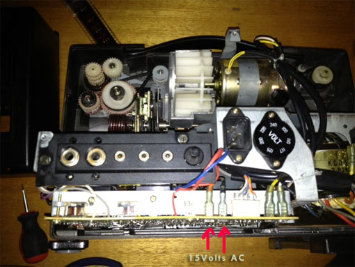
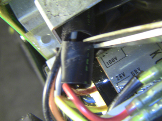
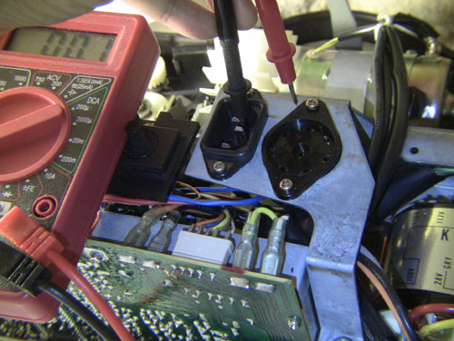
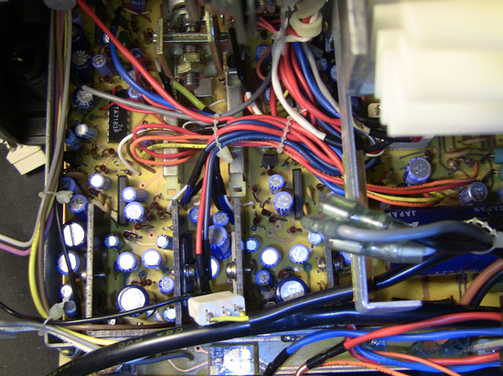
There sure is. See the Red and yellow wires going to the Switch on the far right in your photo (The 'H' switch for the lamp).
Disconnect the power and then pull the red and yellow wires off the switch. Set your meter to AC Volts and place the red probe into the red wire (You should be able to poke it in the end of it into the spade connector). Connect the black probe to the metal chassis of the projector.
Plug the projector in and check the voltage on the meter. It should be around 11V AC on the red wire. Leave the black probe connected to the chassis and stick the red probe into the yellow wire. There should be about 9V AC on the Yellow wire. (Mine are 11.3 and 9.3 respectively). If there is nothing on those, then check that the power cable to the projector is working by using it (and the same wall socket) on another device like an electric kettle or a computer as they usually use the same shape plug. If the power cable and wall socket are OK but the voltages are zero, then the transformer is blown or the wires from the AC socket to the transformer are faulty.
Posted by Janice Glesser (Member # 2758) on July 05, 2013, 12:53 PM:
Well...this projector is reading a BIG ZERO...I think a zombie is more alive
So Pete you are saying it could be the transformer or the wires. Then my totally uneducated guess is the wires. Since the light did work before I blew out something. Is it an all or nothing situation where the transformer either works or it doesn't? OR can some parts work and others not? ... i.e. power gets to the lights through the transformer...but not to the motor?
Is there a possiblity I blew the transformer, since I can't seem to locate any fuses?
[ July 05, 2013, 04:57 PM: Message edited by: Janice Glesser ]
Posted by Pete Richards (Member # 2203) on July 05, 2013, 07:55 PM:
A few ways to find out. Easiest first, from you location I am guessing you are on 110v?
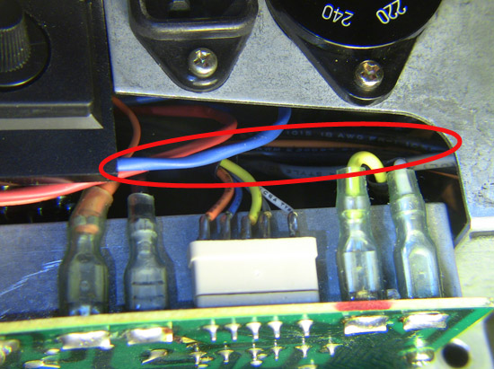
The power goes into the projector via the power socket. From the back of the socket there is a blue wire that goes straight to the transformer, and a brown wire that goes into the Round Voltage Selector. Various wires come out from the voltage selector to the transformer depending on the selected voltage.
So one thing to try, if you are on 110V, remove the pwer cable, then remove voltage selector disc by pulling it straight up, and change the voltage selection to 117V. This would cause the projector to run at the wrong speed but won't damage anything.
Do that then test your voltages again. This will at least check if the wire from the back of the voltage selector to the transformer has burned out. (also check the volatge selector disc for signs of damage when you remove it).
If there is still no voltage present, then remove the power cable. Undo the two screws holding the power socket in, and the two screws holding the voltage selector. You can now pull both of these up to inspect the wires behind them and look for damage.
My projector is now in pieces everywhere too!
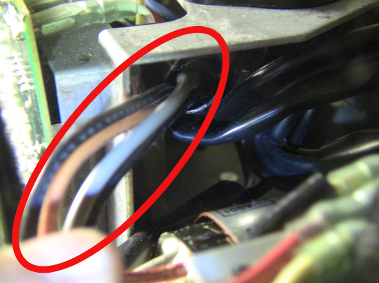
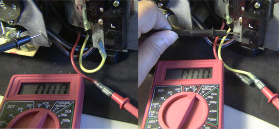
If you can't see any damage then we can check for continuity by testing from the power socket to the centre pin of the voltage selector, and from the earth pin to the projector chassis.
Set you multimeter to continuity (or beep mode if it has it) or to OHMS to check for resistance. Put the probes as per the photos and the multimeter should beep or show almost zero resistance. That will tell us if two out of the three wires are okay from the power socket to the transformer.
Testing the brown wire continuity
Close-up:
Testing the earth continuity
Posted by Janice Glesser (Member # 2758) on July 06, 2013, 12:53 AM:
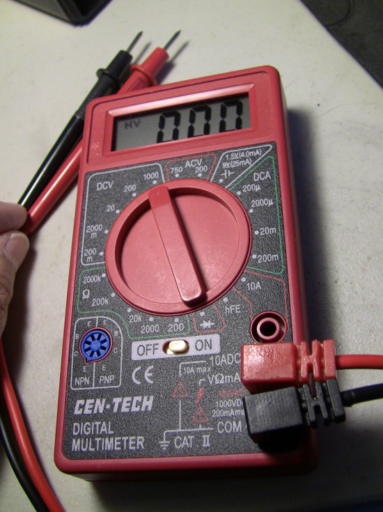
I got a little lost here...I was not sure where to put the dial on the multimeter...This meter was $4.99 from Harbor Freight...very basic.
Here was my guess...
I pulled both the power selector switch and the power socket out...but the wires all looked good.
The power selector switch was already set to 117V,not 110V.
Ground to Chassis Test
Brown Wire to Power Selector Dial Test
Posted by Pete Richards (Member # 2203) on July 06, 2013, 02:39 AM:
Excellent guess!
Those two wires are funtional then.
You may want to unscrew the sockets as per my pictures and check out the blue wire.
I know it sounds silly, but have you double checked that the power cord and wall socket are still working correctly? I spent ages trying to fix something once only to eventually find that I had killed the wall socket!
Posted by Maurice Leakey (Member # 916) on July 06, 2013, 03:51 AM:
Janice
I look forward to your daily reports, I do hope you get there in the end.
I once bought a projector on eBay which looked just perfect out of its box but the troubles started when I tried to use it. My service engineer discovered that just about every soldered joint was dry, and parts of the PCB on the amplifier had soldered sections where the board connections had been damaged.
It is, of course, difficult to spot a dry joint. Possibly it could mean re-soldering every joint.
Good luck to you.
Posted by Pete Richards (Member # 2203) on July 06, 2013, 04:59 AM:
I don't think a dry joint is the issue here. We had a partially functional projector that then got shorted out and has become non functional and has a nuked track on the board.
Dry joints are often a problem in old gear though.
I am worried that the transformer windings have burned out and become open, but hopefully there is a hidden fuse in the wiring that has gone pop!
[ July 06, 2013, 01:28 PM: Message edited by: Pete Richards ]
Posted by Janice Glesser (Member # 2758) on July 06, 2013, 03:40 PM:
Pete...I PM'd you about the schematics
===================
BTW..The lamp IS still working. I think I only blew something in the sound system.
Does this verify that the Transformer is OK?
Since there is no power getting to the PCB because of the damaged section...does that mean we can't test the rectifiers or capacitors? ... From comments others have made... most indicate problems with those components.
The power cord is fine...I have examined all wires...they look fine too.
[ July 06, 2013, 05:32 PM: Message edited by: Janice Glesser ]
Posted by Pete Richards (Member # 2203) on July 06, 2013, 08:42 PM:
That is good news then!
I find that a bit baffling though... Can you check, if you switch the lamp between High and Low output, does it change?
If it does, can you check the voltage on the lamp wires again, the ones next to the H L switch.
It means that the transformer is at least partially working, as the lamp gets its power from there.
There are multiple outputs from the transformer though, and one may have blown. But it does mean the blue wire is okay, and the 240v and power selection wiring is working to get power to the transformer, which is good news.
Can you double check those first two test points I mentioned to see if they are getting the 15v power now?
BTW, the dropbox link didn't work for me. Could you send them via wetransfer.com to me? My email is peter at mudgee dot net thanks!
Posted by Pasquale DAlessio (Member # 2052) on July 06, 2013, 09:33 PM:
Your seeing it unfold here as it happens folks! ![[Eek!]](eek.gif) Live as it happenes with on the scene reports. Three pages of up to the minute news on the dead Sankyo 800. Will Janice be able to save it? Will she get help in time? Stay tuned for the exciting conclusion of "The Sankyo 800" right here on "The Forum"
Live as it happenes with on the scene reports. Three pages of up to the minute news on the dead Sankyo 800. Will Janice be able to save it? Will she get help in time? Stay tuned for the exciting conclusion of "The Sankyo 800" right here on "The Forum"
And now a brief word from our sponsor ![[Cool]](cool.gif)
Hello ! Are you smoking more and enjoying it less? Are you coughing all the time? Then this advice is for you. FREAKING QUIT !!!!
This was a public service announcement.
Posted by Pete Richards (Member # 2203) on July 06, 2013, 10:32 PM:
I know people write 'LOL' all the time, but for once I actually did!
Thanks for the Schematics, I'm going over them now, it will make treating the patient much easier.
I am surprised the lamp is now working, if you could recheck all the voltage points we have mentioned in the whole thread again *while the light is on* that would be great.
Except for the power socket/voltage selector post.
Posted by Janice Glesser (Member # 2758) on July 07, 2013, 01:26 AM:

....and now back to our regular scheduled program.
================
I'll report back on the test with the light ON.
Posted by Pasquale DAlessio (Member # 2052) on July 07, 2013, 09:01 AM:
Hotel 99
We'll leave the light on for ya!
Posted by Janice Glesser (Member # 2758) on July 07, 2013, 06:06 PM:
Thanks Pat...I wish I had an exciting development to report...but it looks like the light is the only thing that is on
Pete...No change in any of the results on testing again with the LAMP ON. The "H" switch does control the light brightness...but voltage still measures .0 with the multimeter on both the yellow and red wires. I'm not sure how that is possible...it has to be getting power. ... AND... Why are there no fuses? I admit to being a bit confused at this point. Do the schematics show any reason for this?
If I were to take this to an electrician...What would I tell them based on the testing we have done already.? Other than the problem on the PCB board...What have we determined?
Posted by Pete Richards (Member # 2203) on July 08, 2013, 04:32 AM:
The schematics clearly show that there should be fuses, they may have been removed by another owner, or your projector is just a different revision.
Just to double check, for the wires on the lamp switch is your meter set to AC or DC?
Before taking it to anyone it would be best for us to check the bridge rectifiers and see if they are blown first.
Posted by Janice Glesser (Member # 2758) on July 08, 2013, 04:45 PM:
If you check the photos from June 5th you'll see the meter is set to ACV 200. It was the same on the second tests too. When I touch the black probe to the chassis there is a little jump...number goes .3 -.0 very quickly. It could be that the voltage is just very low going to the "H" switch. The light does change brightness when moving the switch from H to L... however it doesn't appear to be a significant change in brightness...but then I don't have anything to compare it to. This may be normal.
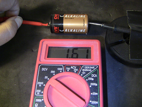
I think the multimeter is operating ok since I'm able to measure battery voltages correctly.
How do you recommend I test the Bridge Rectifier? I can use the little hooks this time...but don't know where to place them and what do I set the meter to. Also, just in case you need me to check the big capacitor next to the Bridge Rectifier... One end is difficult to reach...I would need a right angle probe to test that end. For that matter...I'm not sure if my multimeter measures capacitors
Posted by Pete Richards (Member # 2203) on July 08, 2013, 09:34 PM:
Test the wires near the switch with it set to DC and let me know the results.
Sorry I am not at home at the moment to follow along, I've been in and out of hospital with my daughter. Hopefully will be home soon and can document how to check the rectifier and other components.
Do you have the possibilty of setting up Skype with a camera so I could see what you were doing real time, so to speak?
Posted by Janice Glesser (Member # 2758) on July 08, 2013, 11:26 PM:
Hey Pete, seems you have a lot on your plate right now...this can wait...by all means take care of your daughter. I hope she is ok.
I'll do the switch test on DC and take pictures.
I'll have to think about webcaming the testing...I just don't have a good way to do that right now. I use Google Talk and Google Hangout for web conferencing.
Posted by Mike Peckham (Member # 16) on July 09, 2013, 09:39 AM:
John Capazzo said:
quote:
This isn't the first time I've heard of motors failing on Sankyo machines. It's VERY rare for Elmo motors to fail, but Sankyo machines are almost common.
Which is odd, because Elmo and Sankyo sourced their motors, sound heads and numerous other parts from the same suppliers - in fact the Sankyo 800 motor and the GS 1200 main motor are the same part.
Janice, this thread is a great read, I'm willing that machine to come back to life and looking forward to each new installment. I understand that it's necessary for progress to slow a little whilst Pete takes care of his daughter, but I'm looking forward to seeing you get to the route of the problem.
Good Luck!
Mike
Posted by Janice Glesser (Member # 2758) on July 09, 2013, 01:53 PM:
Thanks for the vote of confidence Mike. I don't think the motor is at fault either...but tracking down the real culprit is not easy.
I'm happy that you and some others find this thread entertaining and hopefully informative...AND if there are more electricians out there ...don't be shy... please join in....all comments welcome
Posted by Steve Klare (Member # 12) on July 09, 2013, 02:14 PM:
No!
This machine must work again!
Epics always end heroically!
Posted by Paul Adsett (Member # 25) on July 09, 2013, 02:43 PM:
Good to see Mike posting again.
Posted by Pete Richards (Member # 2203) on July 09, 2013, 07:15 PM:
We will get it going!!
I wish I was on the same continent and could help out more.
We can test the motor easily enough, I will be back on deck later this week. In the meantime, give those DC readings a go, it will help a lot with what to do next.
Posted by Janice Glesser (Member # 2758) on July 10, 2013, 04:10 AM:
One of the metal probes fell off my multimeter ... so I got a little practice soldering it back on....I think I need to get a little bit better meter. I don't think this one will hold up to too much abuse
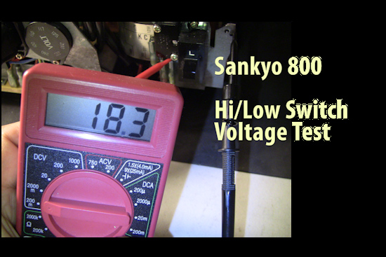
Here is a video of the voltage tests on the Hi/Low Switch wires. The power cord is plugged in and the selector switch set to lamp on. The readings bounced around so much a single photo wouldn't work. I don't even know if I had the meter set correctly...but it was the only way to get any reading.
http://www.youtube.com/watch?v=Td_z42gaHho
Posted by frank arnstein (Member # 330) on July 10, 2013, 10:03 AM:
Hi Janice,
While waiting for fresh ideas, here's something for you to check out and also a possible fuse location for the amp.
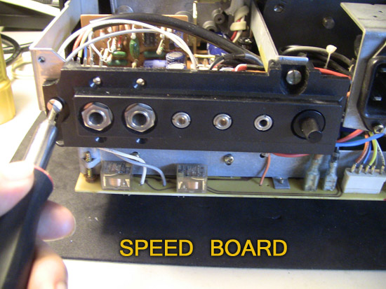
On your 3rd picture the speed board is visible on the left side and it has a big black heat sink mounted on it. Remove the 2 screws that hold the speed board in place and then slide the board out towards the rear. Remove any connecting sockets that may hinder the board from sliding out far enough to turn it over.
Then you can look down at the big amplifier board located underneath. There should be a glass fuse located some-where on that board and it may well be blown.
Next, carefully turn the speed board over to examine the 3 solder joints found underneath, connecting a small black box that is screwed to the heat sink. It has 3 terminals soldered to the speed board any or all of them may have melted, giving an open circuit to the motor. This weird little box gets mighty hot and has to get rid of that heat fast. If not, it just builds up until it melts the solder on its own terminals and then the motor may stop.
Refit and resolder into place any of these 3 that may have melted and then try testing it again after carefully refitting the speed board back in place.
Let us know what you find and anything fresh. Many of us are following this saga with great interest and hope it concludes favorably soon.
dogtor frankarnstein
Posted by Pete Richards (Member # 2203) on July 10, 2013, 06:30 PM:
Thanks for the video, it makes things so much more clear. I will make one up this weekend of testing all the main components for you and show the meter settings etc. I think it is the best way after seeing your vid.
Just a quick note re the meter. It is fine for the task, I'd just buy a better quality set of test leads.
Now with that meter, (sorry if you already know all this) the settings for voltage work like this.
Your meter needs to be set to the maximum voltage you are likely to expect. So if you were testing the house mains power (110v AC in the USA), you would set it to ACV 200, and then it will give the corect reading. If I was to test the mains in Australia (240v) I would have to set that meter to ACV 750, as our voltage is higher than the 200V setting on that meter, so we need to move up to the 750V setting. Now you could of couse test the 110v on the 750V setting, but it wouldn't be quite as accurate.
For the DC Voltage, your meter has settings for 1000Volts DC, 200V DC, 20V DC, 2000millivolts DC (same as 2V DC), and 200mv DC (same as one fifth of 1V).
So if you were testing a 9V battery, you would set the meter to 20V DC. If you were testing a little circuit with tiny amounts of voltage (say 80 millivolts) yoy would set the meter to the 200mv setting and so on.
In this case, the readings you are getting are only a few millivolts, and are swinging around wildly, so something is wrong somewhere.
If you could check your meter is working properly, by setting it to 20V DC and placing the probes on a normal 1.5V battery or a 9V battery and check that you get a reading of 1.5V or 9V on the meter. (ie any standard batteries you have around the house).
If the meter is reading correctly, then I will make up a video for you and we can test all the various bits and track down the problem.
We will be testing some individual componets, like resistors and rectifiers etc. and checking voltage levels across the board in AC and DC. I have a meter with a similar layout to yours, so I will use it.
[ July 10, 2013, 10:18 PM: Message edited by: Pete Richards ]
Posted by Janice Glesser (Member # 2758) on July 10, 2013, 06:37 PM:
Thank you Frank for jumping in here. This helped alot! Removing the speed board revealed another burned out section of the PCB. I still can't find a fuse in this machine. Why would anyone remove them? I also wasn't clear on the "black box" either...but everything else appears ok on the board.
As per Franks instructions: I removed the two screws and then the 5 connecting sockets. I had already removed the 6th socket that attaches to the speakers. (Note: I numbered all the sockets so I could put all the wires back in their right places )
I then pulled the speed board out.
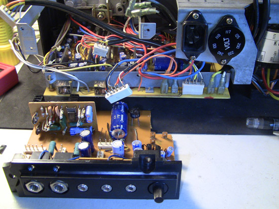
...and flipped it over.
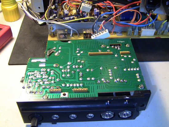
Close-up of bad section on PCB. The Bridge Rectifier is connected to this section.
Examined the sound board...but still can't see a fuse anywhere.
Posted by Pete Richards (Member # 2203) on July 10, 2013, 07:28 PM:
Now that you have the sound board out, we may as well test some components. Do you have some suitable guage wire to repair the broken tracks with? Unfortunately that track has lifted and appears to also to be shorting the other solder junction.
These tracks most likely vapourised when you shorted the voltage rectifier.
I'll be home in a few hours and take some pictures of how to test the various parts now that the board is out.
Oh and I just realised, it looks like the lamp is on even when the projector is in the 'STOP' position. Is that the case?
Posted by Janice Glesser (Member # 2758) on July 10, 2013, 08:21 PM:
Pete, I'm pretty sure the lamp works properly... it was off or at least very dim (I don't remember) in the stop position and it turns on bright (High or Low) in the lamp position.
When it comes time to repair the boards...that's when I'll take it to an electrician. I'd rather have someone with more experience do the PCB repair work and replacement of any components. Hopefully I can do the troubleshooting and identify what needs to be fixed.
I also just bought the service manual which should be helpful.
Posted by Jon Addams (Member # 816) on July 10, 2013, 08:25 PM:
This thread is better than any Alfred Hitchcock movie I have ever seen!
I must admit I have been following and reading each word very carefully as I have 2 Sankyo 800 and 1 - 700 with the same problem. Like Janice, I can't fine any fuses on mine.
One will get you 10 Janice gets this working again!
Jon
Posted by Bruce Wright (Member # 2793) on July 10, 2013, 08:30 PM:
Hi Janice: Do not use the meter in the 200m or 2000m position.
This voltage setting is so low you are picking up stray voltages and need shielded leads for correct readings. That meter you have should work fine. Heck I've burned out several of them. This has been fun reading, and if all else fails you can sell it to me GOOD LUCK bRUCE
Posted by Pete Richards (Member # 2203) on July 10, 2013, 08:43 PM:
When you go to get the boards repaired, if you can't find someone who services projectors, check out guys that modify game consoles (like XBOX/Playstation etc.) they are usually young guys that work cheap and are fantastic at soldering.
Posted by Janice Glesser (Member # 2758) on July 10, 2013, 10:09 PM:
@Bruce... Thanks for the feedback on the meter setting. Looks like I was mistakenly thinking I was getting somewhere ...but Pete said it was helpful for him so I guess it wasn't a complete waste of time. The numbers on the dial mean nothing to me. So I'm just guessing If I keep this up I'll probably blow out the meter soon myself.
@Jon...Have you gone through all this troubleshooting already? This sounds like a design flaw.
Posted by Pete Richards (Member # 2203) on July 10, 2013, 10:17 PM:
If you have a read of my previous post, it explains how the meter settings work. If you do get a chance to test a battery with the meter it to verify it is working properly, that would be great.
There is a good video here:
http://www.youtube.com/watch?v=bF3OyQ3HwfU
Posted by Janice Glesser (Member # 2758) on July 11, 2013, 01:02 PM:
Meter works...
Posted by Pete Richards (Member # 2203) on July 11, 2013, 09:32 PM:
Good stuff, I am just removing my boards now so I can take some pictres.
I accidentally shorted the motor to the chassis and the projector now doesn't run.
Edit: It blew the fuse I circled earlier, replacing it got it going again. Phew!
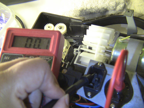
Okay, I would like you to set the meter to 200V AC, and disconnect the two wires in this picture:
Then plug the power into the projector and turn the switch to 'Forward'.
Place the black probe on the Chassis and the red probe into the end of the orange wire. You should get around 8 or 9V AC.
Then try the red probe into the black wire and you should get around 20V AC.
If you get nothing on these, then the transformer is cactus, as these wires come straight from the transformer itself. If there is voltage there, then we can continue on to check board components. If not, then the projector is probably a paperweight unfortunately.
[ July 12, 2013, 04:54 AM: Message edited by: Pete Richards ]
Posted by Janice Glesser (Member # 2758) on July 15, 2013, 03:24 PM:
Pete...I'm sorry I missed seeing this update. I wish there was a way to subscribe to a topic to get email notifications.
Sorry you blew the fuse on your machine...but glad that it was an easy fix.
Remember...I have the Speed board removed and wires that plug into it...Do I need to replace the board first before doing this test?
I'm crossing my figures that I get some kind of a reading...but not holding my breath
[ July 15, 2013, 10:50 PM: Message edited by: Janice Glesser ]
Posted by Pete Richards (Member # 2203) on July 15, 2013, 06:45 PM:
Nope, no need to replace the board, but you will need to remove both the wires from the board before testing them. Put the probe directly into the end of the wire-connector, the other probe to the chassis and plug in the projector.
Basically those wires come straight from the transformer. If there is no voltage on them when they are not connected to the board, then the transformer is broken.
We want to test them when disconnected to make sure the damaged board isn't affecting the readings.
Make sure your meter is set to 200V AC, and you can check it is working by using the probes to test the voltage on the power cable. (Put the probes into the top two holes on the power cable) It should show about 110V AC. If it does then we know the meter works for AC and you can check those two connectors. Let's hope we see the correct voltage on them!
Posted by Janice Glesser (Member # 2758) on July 15, 2013, 11:13 PM:
STAND BY
Posted by Pete Richards (Member # 2203) on July 15, 2013, 11:29 PM:
Holding breath....
Posted by Janice Glesser (Member # 2758) on July 15, 2013, 11:38 PM:
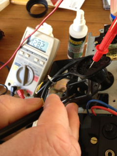
Well Gang...This a deciding moment
Power Cord Test
Transformer Voltage Test
http://www.youtube.com/watch?v=2iRzJeBQWVI
Posted by Pete Richards (Member # 2203) on July 15, 2013, 11:53 PM:
Oh no, It looks like the transformer is blown.
Try it without the 'hook clips' and push the pointy end of the probe into the end of the wire.
Posted by Janice Glesser (Member # 2758) on July 16, 2013, 12:07 AM:
Nothing Pete...We gave it a good go...but I think it's time to let it R. I. P.
Posted by Pete Richards (Member # 2203) on July 16, 2013, 01:33 AM:
Agreed. But you know what? This could still make a good telecine rig.
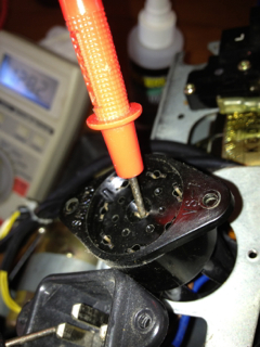
Let's check if the motor still works. You will need a 9V battery, like one of these.
http://www.bunnings.com.au/products_product_batteries-9v-varta-1pk-4122249411_P4410244.aspx?search=9v+battery&searchType=any&searchSubType=products
Okay, all you have to do is disconnect the white and yellow wires from the same board as the wires we just tested (at the far right). You can see that those two wires (white & yellow) go up to the motor.
Push the white wire onto one terminal of the 9v battery, and the yellow wire onto the other terminal. If the motor is okay, it should turn slowly.
If the motor is working, then the projector could be used as a basis for a telecine setup. You could just apply power directly to the motor via those wires from an external DC power supply (like a 'wall wart') and use an LED light source.
If nothing else you could sell it that way if the motor is known to work. I probably know a few people in the US that would give you something for it.
If you wanted to post me the boards I could test and attempt to repair them, but the postage cost probably makes that unfeasible.
Posted by Janice Glesser (Member # 2758) on July 16, 2013, 02:18 AM:
Good idea to test if the motor is working! I don't need a telecine machine...I already have plenty of variable speed projectors and a MovieStuff Workprinter...but if the motor is good and somebody here in the US can use it...that would be great. Repairing the burnt traces on the boards shouldn't be too difficult.
In my optimistic state of mind... I bought the service manual and it just got delivered today. Guess I won't need it now.
Posted by Pete Richards (Member # 2203) on July 16, 2013, 05:32 AM:
I'd be happy to buy the service manual, others would be interested in the front take-up arm for converting an 800 to be able to take 1200ft reels, the motor is also worth something if it is working, so is the bulb and lens. You can probably get a reasonable bit of your investment back if you part it out.
Posted by Paul Adsett (Member # 25) on July 16, 2013, 08:57 AM:

Directed and Produced by Janice Glesser
Technical Advisor Pete Richards
Director of Photography Janice Glesser
Electronic Supplies by Radio Shack
Coffee courtesy of Starbucks
Transportation by bus
Photographed on Eastman High Fade stock
Song: It Stopped Loving Her Today" by George Jones
DVD now available
Look for the book " My Life with a Sankyo" now at all Barnes & Noble bookstores

Posted by James N. Savage 3 (Member # 83) on July 16, 2013, 12:11 PM:
I'm ready for the sequel!!!
Posted by Paul Adsett (Member # 25) on July 16, 2013, 12:19 PM:
Return of the Sankyo ?
Posted by James N. Savage 3 (Member # 83) on July 17, 2013, 06:02 AM:
Or how about "REVENGE of the Sankyo"!
James.
Posted by Pasquale DAlessio (Member # 2052) on July 17, 2013, 06:28 AM:
I want the next one in 3-D!
Posted by Janice Glesser (Member # 2758) on July 18, 2013, 09:20 PM:
EPILOGUE...
Sorry it took me so long to get around to this last test, but I didn't have a 9V battery.
Pete...I think you are going to like this
http://www.youtube.com/watch?v=O94IFQ6ThsM
Posted by John Capazzo (Member # 157) on July 18, 2013, 10:02 PM:
Janice,
I have a transformer for your 800 and years ago when it was sent to me, the seller assured it works. I can test it to be sure, but I'm sure it's fine. It's yours if you want it. If you send me an email, I'll take a pic of you so you can match it up to be sure.
John
Posted by Brian Stearns (Member # 3792) on July 19, 2013, 12:42 AM:
Sankyo Has Risen From The Grave?
Posted by Pete Richards (Member # 2203) on July 19, 2013, 07:45 AM:
Excellent! And I learned a new term!
Well, we know the motor and the mechanicals appear to be okay, which is good news.
Posted by Pasquale DAlessio (Member # 2052) on July 19, 2013, 07:57 AM:
Ka-Puee. You learn something new every day!
Posted by Pete Richards (Member # 2203) on July 20, 2013, 12:45 AM:
What is dead may never die.
Stay tuned.
Posted by Janice Glesser (Member # 2758) on July 20, 2013, 11:53 AM:
I'll be taking a short break from the Sankyo ... up to Oregon next week for a little R & R near Mt. Hood
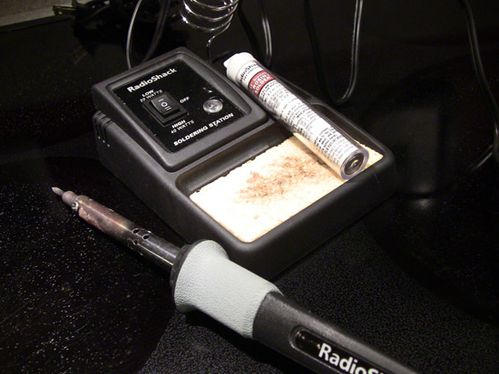
I've pulled out my trusty soldering station in preparation for PCB repair work. OH LORD...What am I getting myself into?
Pete...I'll email you some enlarged pics of the PCBs.
[ July 20, 2013, 01:31 PM: Message edited by: Janice Glesser ]
Posted by Pasquale DAlessio (Member # 2052) on July 20, 2013, 12:15 PM:
Will Janice be able to raise it from the dead?
Will she be back in time to save it?
Will Pete give up on her and call it quits?
Stay tuned right here in "THE FORUM" for the exciting conclusion of "The Death Of The Sankyo 800".
Brought to you in part by ........
Posted by Pete Richards (Member # 2203) on August 05, 2013, 06:23 PM:
The sequel is in production, I have been tied up using the machine (it is my telecine rig) and haven't been able to pull it apart to get the pictures etc. to start on the new resuss effort.
Should be able to get onto it tonight though...stay tuned!
Posted by Janice Glesser (Member # 2758) on August 05, 2013, 08:01 PM:
I'm trying to gather up additional tools to repair the PC boards and thanks to John Capazzo a new transformer is on it's way.
I just bought a solder sucker to remove the old solder, but I need to get some flux. I'd like to get a flux pen since I don't need much but there are different types of flux....what should I get?
Pete...I also need some specs on the components I need to replace so I can locate and order them...i.e. bridge rectifier, capacitor, and fuse.
[ August 05, 2013, 09:40 PM: Message edited by: Janice Glesser ]
Posted by Bruce Wright (Member # 2793) on August 05, 2013, 08:57 PM:
"FLUX" ARE YOU KIDDING ME? "FLUX". Make that Rosin.
And some 63/37 rosin-core solder .050 diameter or smaller.
As a point of interest, is that a variable wattage soldering iron ? Good luck. Luck is better than skill every time. Don't
you just love this forum.
Posted by Janice Glesser (Member # 2758) on August 05, 2013, 09:28 PM:
The iron has dual settings...Low 20watts - High 40watts.
The solder I have is 60/40 Rosin Core .032 diameter
Will this work for the flux?
http://www.radioshack.com/product/index.jsp?productId=12582876&locale=en_US
Posted by Pete Richards (Member # 2203) on August 05, 2013, 10:27 PM:
Yes that flux pen will work fine. I don't bother using it on connections of this size, but it will probably make it a bit easier.
When desoldering I find it easier to add a bit of fresh solder first to the joint, it seems to make it easier to get the old stuff out.
I'll be pulling the board out of my '800 tonight and getting all the details for you Janice.
I'm guessing that is 0.032 of an inch?? Anything 1mm or less in diameter is ideal.
Posted by Bruce Wright (Member # 2793) on August 06, 2013, 05:23 PM:
The 60/40 solder is ok. The 63/37 goes from a liquid to solid faster and helps reduce poor (cold) solder joints. I don't use
flux. Good idea on adding small amount of extra solder. My soldering iron is 25 watts. The main thing is to have 3 or
4 flat sides on the tip BUT no sharp point. Sharp points don't
allow enough surface contact for good heat transfer.
Have the "solder sucker" right down on the joint-apply heat-
when solder melts push the button. Sometimes we get lucky and
it works.
Posted by Pete Richards (Member # 2203) on August 07, 2013, 07:46 PM:
Just noticed Janice has 911 posts! Seems appropriate at the moment.
I am transferring some photos and measurements now.
Posted by Pasquale DAlessio (Member # 2052) on August 07, 2013, 08:01 PM:
Only here on "The Forum" do you get such a detailed report on the ongoing saga of "The Dead Sankyo 800". Will it be reborn? Will it become Frankensankyo?
What a man!
What a woman!
What a mess!
Don't miss the exciting conclusion of this exciting saga. Here on "The Forum"
This message was pre-typed!
PatD
Posted by Janice Glesser (Member # 2758) on August 07, 2013, 09:23 PM:
GULP!
Posted by Pete Richards (Member # 2203) on August 11, 2013, 10:44 PM:
Okay, the fuse is 250v 4 Amps and approximately 20mm long and 5mm in diameter (I have nothing that can measure in imperial units, sorry).
The capacitor is 1000uf 50V 85 degreesC axial electrolytic.
The rectifier is a Toshiba 1B4B1 Bridge Rectifier. It might be the same as this one.
http://tinyurl.com/m3bnsf2
Note the electrolytic capacitor and the bridge rectifier must be replaced 'around the right way'.
The bridge rectifier has two pins for AC input and two pins for DC output, one negative, one positive (i.e. it takes the AC voltage and puts out DC voltage)
The Capacitor has a positive end and a negative end, and must keep the same orientation as your existing one.
Posted by Janice Glesser (Member # 2758) on August 12, 2013, 01:42 PM:
Thanks Pete. So far I think I've located these parts:
FUSE
http://www.frys.com/product/5850423?site=sr:SEARCH:MAIN_RSLT_PG
FUSE HOLDER
http://www.frys.com/product/5864503?site=sr:SEARCH:MAIN_RSLT_PG
CAPACITOR
http://www.frys.com/product/1710221?site=sr:SEARCH:MAIN_RSLT_PG.
Let me know if these are correct.
The BRIDGE RECTIFIER is a bit more illusive. If there is someone from the forum who has replaced this part, could you direct me to a supplier or do you have an extra one to sell? Perhaps there is an alternative part?
Posted by Maurizio Di Cintio (Member # 144) on August 12, 2013, 03:58 PM:
The rectifier is a common electronic component: unsolder the orginal and take it to a Radio Shack or something; they should be able to supply you a similar one. You are paying ridicolous prices for these items, espcially the fuse; generally they cost a buck or less each, plus you dont' have to replace the fuse holder.
Glad you are progressing on the winding path of the "Sankyo Resurrection Experience"...
Posted by Janice Glesser (Member # 2758) on August 12, 2013, 06:32 PM:
There are two electronic stores in my area...FRY'S and RADIO SHACK. I don't know how often any of you have ever looked for help from the people that work at these places...but in my experiences most have very little technical knowledge. So I try to be as specific as I can to make sure I purchase the correct component.
Do any of these match the specs of the rectifier I need? Also, I'm curious...do the amps and voltage need to match the original specs exactly? For example...What if the amps was 2.0a instead of 1.5? Would that be bad?
http://www.radioshack.com/product/index.jsp?productId=2062581#tabsetBasic
http://www.westfloridacomponents.com/DI076/1.5A+1.5+Amp+100V+Bridge
+Rectifier+W01-404.html
http://www.westfloridacomponents.com/G361APF04/1.5A+100V+S ingle+Phase+Bridge+Rectifier+General+Instruments+W01G.html
@Maurizio...This machine has no fuses nor fuse holders...not sure why.
[ August 12, 2013, 10:04 PM: Message edited by: Janice Glesser ]
Posted by Pasquale DAlessio (Member # 2052) on August 12, 2013, 07:30 PM:
2.0 will be fine. As long as the rating is higher it is OK.
Posted by Janice Glesser (Member # 2758) on August 12, 2013, 09:46 PM:
What about the voltage? Can it be higher?
Posted by Craig Jarvis (Member # 3856) on August 13, 2013, 12:38 AM:
Hi, I had an electronic repair shop for about 15 years. I hate to say this, but I would load it up and take it to the local TV guy. He would quickly be able to meter the bridge rectifier and assess whether it got cooked. I don't know the position of the cap but they usually have a pregnant look to them if they are bad. The exception is a filter cap and they just produce hum when shot. If you shorted out your leads when testing and now have nothing I would say the first place would be the mains fuse which would shut down everything. The pop you heard at first from the speaker is DC leaking. There isn't a ton of voltage in the circuit but...........it's my experience some of these projects go from bad to worse. Good luck with it.
Posted by Janice Glesser (Member # 2758) on August 13, 2013, 02:23 AM:
Thanks for joining the thread Craig We could use your expertise. I'm not adverse to taking it to an electrician...but they aren't cheap and I already have a good amount invested in the machine. I agree I could potentially do more harm than good...I proved that already. But, no matter the outcome...this is also a learning experience and a challenge for me and for all who have contributed to the project especially Pete Richards.
When you say 'Cap' are you referring to capacitor? The Capacitor in question is positioned just to the left of the Bridge Rectifier (photo on page 1). The Bridge Rectifier or the Capacitor do not appear to have any physical damage. How can I determine if they are bad or not. Is there a test I can do with my meter?
Posted by Brian Stearns (Member # 3792) on August 13, 2013, 03:06 AM:
The only way to fix this is to pull a Frankenstein next time its lightning out put it on you roof and allow lighning to strike it. "Its Alive"
Posted by Brian Stearns (Member # 3792) on August 13, 2013, 03:07 AM:
The only way to fix this is to pull a Frankenstein next time its lightning out put it on you roof and allow lighning to strike it. "Its Alive"
Posted by Craig Jarvis (Member # 3856) on August 13, 2013, 10:19 AM:
Hi Janice. I didn't mean to discourage you but all the electronics and capacitors and bridge rectifiers can be confusing. Yes, cap is lingo for capacitor. Sometimes they don't appear bad and the only thing that truly tests them is called an ESR meter that not many people have, good thing is they're cheap and easiest to just swap out if you have concerns, same for the bridge rectifier. You can check the bridge by putting your meter in diode test (looks like an arrow >| kinda. Meter back and forth across the terminals and note a beep and any of the positions. Without seeing the schematic I would think there would be one main power supply and there would be another totally separate for the motor control. This would be somewhat smaller and have an IC (integrated circuit) on it or a large transistor that regulates the motor speed. I am new (as of last week ) to projectors but have fixed many reel to reel tape machines that employ the same electronics to regulate motor speed. Like I mentioned, when you arched your test leads and got the sparks testing your motor.... the mains fuse likely went killing all the subsequent circuits. You have to get the machine back to pre zap state before you can figure out the motor issue. Whatever fuse lays just inside near where the power cord comes into the unit will be the mains fuse. Swap that out, hit the switch and see if your pilot like at least lights up now. Keep me posted.
Posted by Pasquale DAlessio (Member # 2052) on August 13, 2013, 11:36 AM:
Craig
WELCOME TO THE FORUM!!
Someone with your expertise will be greatly appreciated.
PatD
Posted by Craig Jarvis (Member # 3856) on August 13, 2013, 12:39 PM:
Thanks PatD. I went back through some of the posts and I see lots of what I said had been looked at already. Fresh set of eyes and perspective never hurts. While I'm thinking about it. Janice, try getting your parts from Digikey, I dealt with them lots and they always had the odd stuff I was looking for. One old trick is to just use your nose.... don't get too close and just sniff around the area in question to see if you smell anything burnt. also, gently tapping any area with components with the plastic part of a screwdriver sometimes shows up bad solder joints that may be the problem. Your testing always starts something like this, cord, mains fuse, power switch then move on to the first board the wires from the switch go to metering all on the AC position and range on your meter set to "200". when you start seeing caps and diodes switch to DC position in the 20 position likely. Your meter will tell you if you're out of range. Keep us posted. I have no idea the inside of your machine but I'm a troubleshooter.
Posted by Janice Glesser (Member # 2758) on August 13, 2013, 12:44 PM:
Craig, I realize this is a long thread and if you haven't read thru each step it can get confusing. Here's a bit of a summary to get up to what we know and where we are to date.
TESTING RESULTS
1. The motor is good.
2. The transformer is bad. I bought and received a replacement transformer.
3. There are 2 areas where the PCB traces are burned out...one on the top speed/audio board and one on the larger lower board effecting power to the motor.
4. I early on shorted something out on the speed board while attempting to meter the Bridge Rectifier. This knocked out the audio.
5. The lamp still works.
6. Despite popular opinion....There are NO FUSES that I can find in this projector.
=======================
NEXT STEPS
Working with Pete Richards in Australia here is the current plan of action. Please correct me if I'm wrong on any of this Pete
1. Repair traces on the 2 PCBs.
2. Replace the existing wire with a fuse holder and fuse on the speed board.
3. Replace the Bridge Rectifier.
4. Replace the Capacitor next to the Bridge Rectifier
5. Replace the transformer.
Posted by Craig Jarvis (Member # 3856) on August 13, 2013, 01:40 PM:
I only have one word. Wow! I wish you the best of luck. Transformer was bad? just want to check with you, are you sure your meter was on ac and not dc? and that you were measuring across the the centre tap to any of the leads on the secondary? I don't want to stir things and I just want to help. But power transformers don't usually go, especially ones from that era. Never say never but.......let me know how you make out.
Having said that if there were no fuses in the unit it could happen, it's just the DC side usually melts quickest and after it blows the main part stays on. I think you have a handle on things. Always probe circuits with one hand.
Posted by Bruce Wright (Member # 2793) on August 13, 2013, 02:52 PM:
A 'fuse clip' is different from a 'fuse holder'. A 'fuse clip'
is only one end of a 'fuse holder'. Or that's the way it is in
my part of the world. Good luck.
Posted by Janice Glesser (Member # 2758) on August 13, 2013, 07:22 PM:
Bruce if you click on the link I posted for the fuse holder you will see they are clips. I was just using the term "fuse holder" as a generic reference for the part and the term I used in my internet search.
Posted by Pasquale DAlessio (Member # 2052) on August 13, 2013, 08:22 PM:
1. Repair traces on the 2 PCBs.
2. Replace the existing wire with a fuse holder and fuse on the speed board.
3. Replace the Bridge Rectifier.
4. Replace the Capacitor next to the Bridge Rectifier
5. Replace the transformer.
6. Get rid of projector.
Posted by Craig Jarvis (Member # 3856) on August 13, 2013, 09:25 PM:
PatD, you are thinking the way I'm thinking. I hate to say it but it's not worth the effort, time or money. Sorry. Tough pill to swallow but I have been there more than a few times.
Posted by Pete Richards (Member # 2203) on August 13, 2013, 11:41 PM:
I personally would repurpose it as a telecine setup, you have a nice motor and the mechanics still work, and that motor is easily speed controlled down to 1 or 2 fps just by dropping the voltage.
But Janice already has telecine machines all over the place
I look at trying to repair it as a fun adventure/learning exercise, it would probably be less hassle to buy a mechanically broken 800 and swap out the boards.
There has been many a time I have whiled away far too many nights repairing something I probably should have thrown out, but I enjoyed the journey and learned a bit along the way, so it was (kind of) worth it in the end.
Posted by Janice Glesser (Member # 2758) on August 13, 2013, 11:52 PM:
I'm going to ignore Pat and Craig's posts because they are non-constructive. It's my time and my money so why not be supportive. None of the things listed on the repair list is beyond doing. I'm currently talking with a former co-worker who is interested in helping me and Pete has been very generous with his time to help troubleshoot the issues. He obviously wouldn't be doing this if he didn't feel it was worth the effort.
So please...you may personally think this is a futile project, but maybe refrain from such defeating comments.
Posted by Dominique De Bast (Member # 3798) on August 14, 2013, 02:09 AM:
I am with you, Janice. A French site recommand not to transform projectors in telecine as if too many people do so there won't be projectors left for the next generations to project reel films. Saying that, they value each projector. I think also that each projector wich can be fixed or kept well working should be, even if it is easier or cheaper to thrown it away and buy another one. You get my full support on this project, Janice.
Posted by Maurizio Di Cintio (Member # 144) on August 14, 2013, 05:29 AM:
Hello all. I agree 100 % with Dominique. Please, Janice, do not give up!!!! I've seen projectors which were in a stae worse than this one's, which were brought to 100% efficiency. So don't give up. You can do it.
Posted by Craig Jarvis (Member # 3856) on August 14, 2013, 01:02 PM:
Sorry, I didn't mean to be defeating. If you and the people helping have any electronic based questions feel free to ask. I retired from that now but I can shed insight on older electronics.
Posted by John Selph (Member # 3366) on August 14, 2013, 05:37 PM:
Janice, I repair a lot of computers and to expound on identifing bad caps you need to look for swollen and leaking caps. If you see any bulging of the capacitor body, or any black or brown "crud" on the component, then it is probably bad. Ironically, I see this on motherboards quite a bit, and the computer still works, but will usually fail within a short period of time. Also, be sure to disconned the AC and discharge any caps that you will be working on, or around. They do "bite"!
John
Posted by Phil Mitchell (Member # 3876) on July 01, 2014, 04:40 AM:
Is it me Janice or is your 800 expoericing similar issues to our 600's?
Peter from Australia, do you mind asking me where in Australia you are, I am in Melb Northern Suburbs. as maybe you know more about this than I or know someone in Melb who can check this sort of thing.
You can MSg me if you like, I have a 600 that just stopped running, I am hoping it was where the brushes connect to motor as I noticed a spring was missing for white cable and a bit of dust and fluff came out.
Got some new springs, brushes look okay, but going to have to wait for a mate of mine who has smaller hands and not effected by arthrtis to put them back on again.
The blue and white wire does have power according to my meter.
Cheers
Phil
Posted by Janice Glesser (Member # 2758) on December 10, 2014, 04:35 PM:
Although I don't really have any good news to add to this thread...I thought I would update this saga with my recent activities.
I did the repairs to the two PCB's which came out fine.
After the repairs... I re-inserted the speed board and re-attached all the connections...so far so good. But then I plugged in the power cord...OH NO...some obnoxious smoke started bellowing out of the machine. Didn't seem to be coming from anything in the area of my repairs. Pulled the plug...tried not to breath in the fumes... and got out of the room. Some air freshener helped with the horrible smell...but nothing seems to be helping my poor projector.
To say the least....I'm a bit discouraged at this point.
Posted by Barry Fritz (Member # 1865) on December 13, 2014, 09:55 PM:
Regarding purchases from Ebay, persons that sell films truly may not know much about them. They may have purchased them at a sale and are just reselling them. Projectors however, are a bit different. Most anybody can plug them in and if they hear the motor/fan running and if the lamp lights, they assume it is working just fine and may state as much in the ebay ad. It is incumbent on anyone purchasing a projector to ask questions. I always ask if it has been tested with film. If it is a sound machine I ask if has been tested with sound film. If not tested with film do the sprockets and reel spindles spin as they should in forward and reverse. I ask if there is any sound from the amp and/or speaker when the volume and tone are adjusted up. If you don't ask these questions, you are really rolling the dice on an Ebay purchase. Based on the problems Janice has found with her projector, that seller clearly knew it did not work properly.
Posted by Mathew James (Member # 4581) on December 14, 2014, 08:58 AM:
Hi All,
Read the thread from start to finish. Thrilling!!!
Sorry Janice how much trouble this has been.
If the original ebay advert said it powered on, yet the lights and spindles didn't work...I would, like you, think it was an easy fix.
I've bought 2 machines from ebay, both from 100% feedbackers(that is my new rule unless i personally look at their negatives and see that some people are just mean and leave negs for nothing than i will still consider them 100%). I have been fortunate because:
a) The machines were not this problematic
b) This forum help immensely
All i see now is that all you have purchased was an education, an education of how a sankyo 800 looks inside
I really hope you don't give up, even though it has taken this long, but will understand if you throw in the towel on this one...
Did you get the new transformer??
Cheers,
Matt
ps: I agree some ebayers really are clueless with what they sell. Case in point...my new st1200HDM came in a box filled with those annoying pink foam packaging pieces.....just a box with a projector inside filled with those pieces. took me an hour to blow out the machine with compressed air!!!!!Ridiculous
Posted by Janice Glesser (Member # 2758) on December 14, 2014, 09:25 AM:
Thanks guys for the comments. At this point I've pretty much put the whole Ebay transaction scenerio behind me. Live and learn... and I have learned a lot. I had never done any soldering before or used a multimeter. Now I have done both and it was fun. I still don't understand much about electronics...but I know enough now to ask better questions from the experts here.
Matt, I do have a new transformer, which I haven't installed yet. I was waiting to repair the PCB's which I've done. However, the recent incident with the smoke has made me reluctant to move on. I also wanted to replace the Bridge Rectifier and it's adjacent capacitor. The capacitor I can get easily...but the bridge rectifier is a mystery. I don't have a clue to what I can use to replace it.
Posted by Mathew James (Member # 4581) on December 14, 2014, 10:37 AM:
I'm like you..just dabble here and there with a multimeter, but really don't know enough about it to be totally confident.
I think what you need going forward, before turning on any more power etc...is, once the pcb is fixed and then replace the bridge rectifier, find out from the gurus here what order you can safely turn things back on, so as not to re-fry anything.
The last thing you want is to blow that new transformer(if that is possible). I am more worried about your safety of course! So far you are doing good.
The fact that Pete even blew a fuse, and he knows what he is doing, shows how easy it is to mess up.... Such a scarey project, but i agree- FUN!!
I will watch in anticipation as well...with popcorn in hand... Here in Canada, Radio Shack is now 'The Source' which i nowhere as good as radioshack used to be here, but they used to carry rectifiers and such. I am sure someone here will have an extra one that will work for you!
Cheers,
Matt
Posted by Janice Glesser (Member # 2758) on December 14, 2014, 11:05 AM:
I forgot...I also need to insert a fuse holder and fuse where just a wire is right now. I think I'll revisit this in a month or so. Time to enjoy the holidays right now
Posted by Joe Balitzki (Member # 438) on December 14, 2014, 10:58 PM:
I'm sure Janice will triumph eventually because she is our 8mm BOND GIRL
Rumor has it that she will be offering her own T-Shirts with her picture on them next year. In the picture, she is painted Gold, wearing a Gold Bikini, and caressing a Elmo Super 8mm Xenon Projector...
Posted by Janice Glesser (Member # 2758) on December 15, 2014, 01:26 PM:
Joe...You are making me blush AGAIN. A photo on a T-Shirt... possibly, but a gold bikini...OMG...I don't think you want to see that Let's just leave it up to your imagination and so will I. I'm glad we can have some fun in the midst of utter disappointment in working on this projector.
Posted by Joe Balitzki (Member # 438) on December 17, 2014, 09:50 PM:
I'm glad I was able to make you smile and dissipate some of your frustration!
Posted by Janice Glesser (Member # 2758) on May 04, 2015, 02:00 PM:
Update It's been a few months...but yesterday I revisted my Sankyo 800. I got brave enough to remove the bridge rectifier and the big capacitor. It also looks like I have found replacements at my local Fry's Electronics store along with fuse holders and fuses.
After the last test that went up in smoke...I can now see a crack in the bridge rectifier. I think I'll buy 2...just in case I blow it again
Out with the OLD...
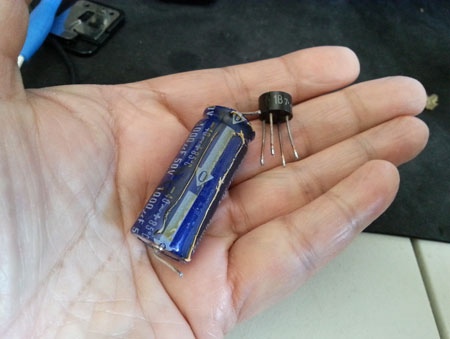
In with the NEW...

[ May 04, 2015, 07:00 PM: Message edited by: Janice Glesser ]
Posted by Steve Klare (Member # 12) on May 04, 2015, 07:12 PM:
Godspeed, Janice!
Remember: that capacitor has a polarity and if you install it reversed you will be back to square one!
You can check out a bridge rectifier with your ohmmeter too. With the (-) lead on the rectifier + terminal, you should get low ohms from the (+) lead applied to either "~" terminal, but high with the (+) lead on the plus terminal and (-) on either "~".
Then you do same on the negative terminal but the readings are the opposite of what they are above.
Posted by Janice Glesser (Member # 2758) on October 21, 2016, 10:49 PM:
UPDATE: It's been about a year and a half since I worked on my Sankyo Stereo 800. The last time I plugged in the power cord black smelly smoke bellowed out. This was very scary. I had bought some replacements components...but my lack of experience made me hesitant to proceed installing them. However after successfully repairing the PCB on my Sankyo 600 I felt a lot more confident with my soldering skills and pulled my 800 off the shelf to finish soldering in the new parts as was recommended.
I had repaired the broken traces on the two boards and installed new: 1) 1000uf 50V Capacitor 2) Bridge Rectifier 3) Fuse holder and fuse.
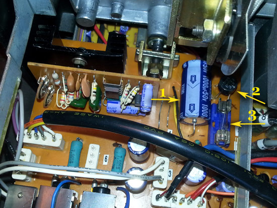
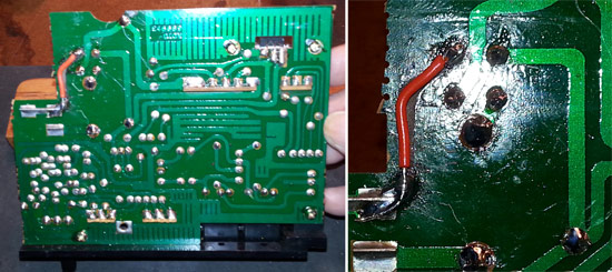
The only thing left now was to plug it in and test it. I opened the garage door in case there was a occurrence of the black smoke. But this time I plugged it in and no smoke. Turn on the Forward switch and presto the motor started and takeup spindle turned. Turned on the lamp and the bulb lit up It was a great feeling since this machine hadn't run since the day I received it.
ALL IS NOT SUCCESSFUL HOWEVER ...
The downside to all this is that there is NO SOUND. No sound from the speaker or from the external speaker plug. When I plug in the power cord on other sound machines I ususally hear a pop...but not hearing anything on this machine. I remember hearing a pop when I first got the projector. However during my testing early on I shorted something....but don't know what that was.
At this point I need to change my troubleshooting focus to the sound issue. I've tested the projector with sound film and everthing other than the sound works great.
Any suggestions on troubleshooting this sound issue would be greatly appreciated.
[ October 22, 2016, 12:46 AM: Message edited by: Janice Glesser ]
Posted by Andrew Woodcock (Member # 3260) on October 21, 2016, 11:52 PM:
Simple suggestions to begin with, but have you checked your amplifier internal fuse(s)?
With the previous issue and short circuit resulting, I'd start right at the beginning with this one and check power is even getting to that board initially.
Beyond that, you'd just have to check your way through it with a schematic and known test values (voltages) if your drawings have them on.
At least now, you're in a safe position to have power running through the machine to be able to identify these aspects easier, beyond the fuse of course.
Posted by Phil Murat (Member # 5148) on October 22, 2016, 01:55 AM:
Hello Janice,
This is a new Troubleshooting chalenge !!!
I don't know this projector but , this is is a Stereo Machine, so (PROVIDING FUSES ARE OK AND PCB TRACKS TOO...):
- Did you observe lack of sound for Main or both Chanels ?
- There is a low probability both chanels fail in same time but it could be possible if too much current go to the Power Stage Amplifier.
- What kind of Technologie is Power Amp (Hybrid or Classical Transistors)
- What is the condition of Capacitors working for Power Amp.
NB
What is the power of your soldering Iron ? A 15w / 20w is ok.
If "Sankyo" 800 features an "AUX" plug , try to plug it to an outside amplifier (HI FI device) to check sound available and quality.
Let us know
[ October 22, 2016, 04:20 AM: Message edited by: Phil Murat ]
Posted by Andrew Woodcock (Member # 3260) on October 22, 2016, 02:09 AM:
I don't know this particular either Phil but I'd guess it would utilize an STK chipset similar to the GS1200 or like many other machines from that same era.
Posted by Phil Murat (Member # 5148) on October 22, 2016, 04:21 AM:
Hi Andrew,
Some of them are still available (but no longer) .......in former stocks !!!
Posted by Andrew Woodcock (Member # 3260) on October 22, 2016, 04:39 AM:
Yes Phil, I know. Hopefully janice will find her problem before this stage. From the way she describes things, I am guessing she has no sound from either channel Phil, hence my early suggestion...but we shall wait to hear back from Janice on this one.☺
Posted by Janice Glesser (Member # 2758) on October 22, 2016, 03:36 PM:
Yes Phil ... this could be challenging, but if I can get the sound working again this will be a super nice machine. I've come this far...don't really want to give up now
quote:
- Did you observe lack of sound for Main or both Chanels ?
Yes...no sound from either channel...no humming or static...nothing.
quote:
- There is a low probability both chanels fail in same time but it could be possible if too much current go to the Power Stage Amplifier.
The problem I'm having is that I'm not sure where the Power Stage Amplifier is located. Would you be willing to take a look at the schematics and wiring diagrams if I emailed them to you? It may save a lot of guessing and the boards on this projector are infinitely more complex than the Sanyko 600
quote:
- What kind of Technologie is Power Amp (Hybrid or Classical Transistors)
My guess would be Classical...but don't really know the difference. Perhaps the schematics will provide you that info.
quote:
- What is the condition of Capacitors working for Power Amp.
When I identify the Power Amp I'll inspect the caps.
quote:
What is the power of your soldering Iron ? A 15w / 20w is ok.
My iron is 20w.
quote:
If "Sankyo" 800 features an "AUX" plug , try to plug it to an outside amplifier (HI FI device) to check sound available and quality.
I did try the external port with portable speakers with no sound...I'll try the AUX port...but I don't think power is getting to the amplifier.
Andrew: I know this is a very lengthy thread, but if you refer back a few pages you will see that my particular machine did not have any fuses ...except for the one I just installed. There were just wires. So no protection. The sound blew when I was testing the bridge rectifier with the power plugged in and accidentally hit the metal brace with one of the DMM leads.
[ October 22, 2016, 09:19 PM: Message edited by: Janice Glesser ]
Posted by Andrew Woodcock (Member # 3260) on October 22, 2016, 11:47 PM:
Ah thanks Janice. As you say, I did miss that point because of the length of the topic.
As you quite rightly point out, you need to establish first why no power at all is getting to the amplifier stage.
It's unusual for there to be no protection to this part of the machine though. Very unusual in fact unless it uses electronic fuse protection?
Posted by Phil Murat (Member # 5148) on October 23, 2016, 12:04 AM:
Hi Janice,
Here is a typical "Hybrid Stereo Power" Module and curently available in the 80's :
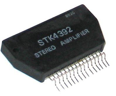
This one offers something like a 50W power
May be I miss something, but when "AUX" out signal is picked up, "Power Amp" is automatically deactivated as signal is just comming from "PRE AMP" module.
Moreover ,If installed, that means "VU METER" needles are moving during "Playing" operation even if Power Amp deactivated.....
[ October 23, 2016, 02:03 AM: Message edited by: Phil Murat ]
Posted by Janice Glesser (Member # 2758) on October 23, 2016, 04:32 PM:
Phil...
OUTPUT JACKS
Speakers, headphones, DIN, LINE OUT.
INPUT JACKS
Microphones, DIN, AUX.
The track power indicator light(s) should light up when plugged into the AC. Photo shows that is not happening.
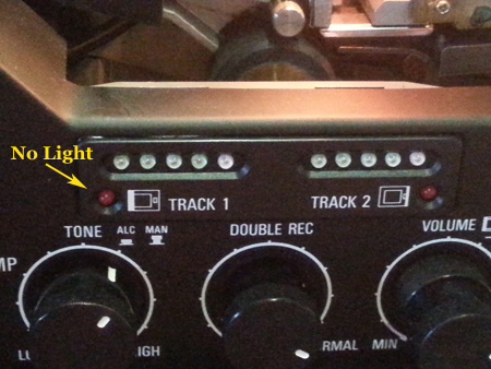
Here is also a picture showing partial components of the bottom PCB. There are serveral IC's placed all over this board. You can see an IC marked TA7183P from this view, however the user manual says the amplifier consists of 13 IC's...11 silicon transistors...and 14 diodes No where in the parts lists is there a single IC labeled "amplifier". So you can see it's difficult for me to know what area(s) to begin checking.
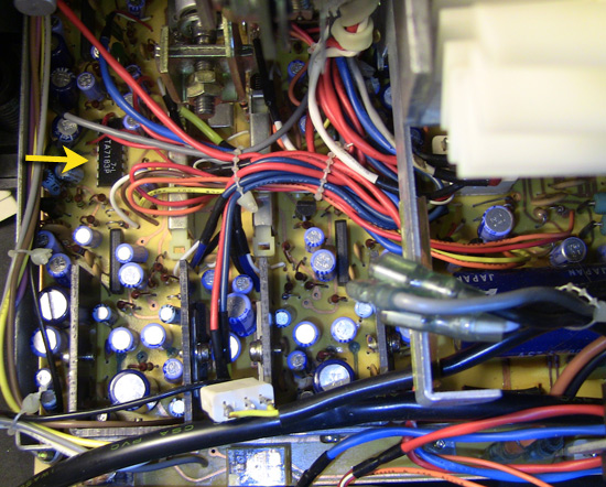
I previously did a trace repair going to the power connector. I have checked continuity on that trace and other connections in that area which all check out fine. Since the motor is running then the main power is ok. Any suggestion on testing power going to the amplifier?
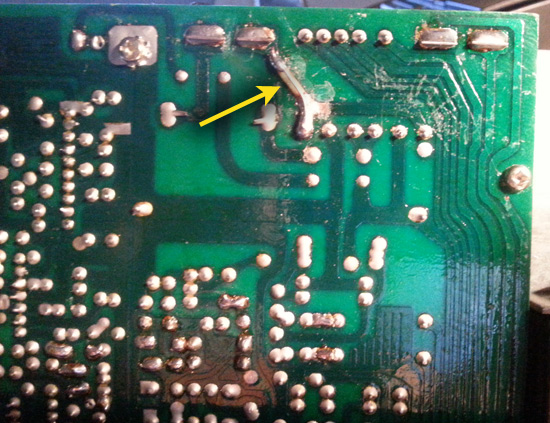
If anyone with electrical knowledge wants to chime in here please do so. I don't think you need to know about this particular machine to provide basic troubleshooting knowledge. I would be happy to send schematics and wiring diagrams to anyone who would be willing to take a stab at deciphering them for me. The pages of diagrams themselves are very detailed...but not labeled as per function.
[ October 23, 2016, 10:43 PM: Message edited by: Janice Glesser ]
Posted by Phil Murat (Member # 5148) on October 24, 2016, 02:29 AM:
Hi Janice,
Due to the pictures, I observe the PCB is Dual lays .
So tracks have to be checked for each side.
No light when machine plugged on means probably no power feeds the Main Sound Card.
I can see also some funny discoloration for some areas on PCB.
I suggest solderings and tracks to be thoroughly check for tiny cracks using a magnifying glass (X3 minimum !!!)
Let us know
Posted by Paul Browning (Member # 2715) on October 24, 2016, 06:50 AM:
Janice your latest photo shows two near identical sets of components side by side, with a sliding switch between them, check these upright transistor numbers, as these may be your output transistors, or drivers?. I 'm surprised this does not have the module type stk module fitted as it looks quite a modern machine.
Posted by Janice Glesser (Member # 2758) on October 24, 2016, 03:44 PM:
Phil...Double layer PCB...That explains the two layout diagrams in the service manual. Oh boy...I certainly hope there isn't any more problem with the traces...repairs could get tricky.
Paul...Good eye! I never noticed the duplication of components. Since it's a stereo machine...that would make perfect sense. I'm not sure where you see the switch and which transistors you mention. I can make a guess and post a pic, but it would be easier if you had the PCB layout for reference.
I'm hoping the components that need checking/replacing are in the visable area of the board...otherwise it may require removing the bottom board which looks very complicated.
Posted by Janice Glesser (Member # 2758) on October 24, 2016, 07:57 PM:
This thread is picking up again I'm sure a lot of my viewers have moved on to other shows...but I hope a few that saw the beginning of the project can tune in again..it's not over yet.
Paul...I think your observation has been very helpful. However to me it appears that these twin sections are probably the input/recording modules. They are connected to the Record switches and all the input sockets.
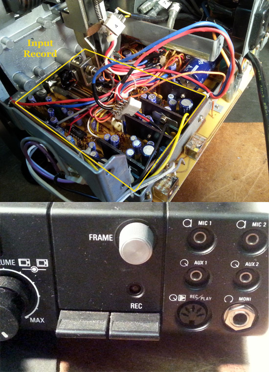
So if that side is the inputs...by deduction the other side should be the outputs...correct? So I started to look around the power pins. It's very difficult to see with the transformer and bundled wires butting up to that portion of the board...but I did spot something suspicious around the big 4700uf 25v capacitor. There's a dark liquid stain under the cap and the traces don't look broken...but more look like acid was poured on them. Also...the schematics show there should be a fuse where the black wire is located.
Any thoughts...anybody?
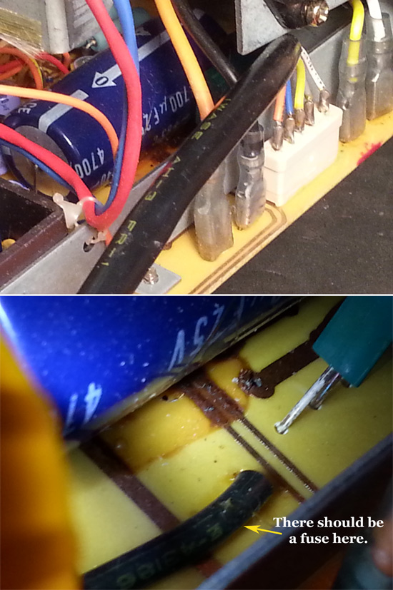
[ October 25, 2016, 03:05 PM: Message edited by: Janice Glesser ]
Posted by Phil Murat (Member # 5148) on October 25, 2016, 02:06 AM:
Hi Janice,
The stain below Big Cap is suspicious, so......
1) Tracks involved seems to be corroded within stain...
2) Unfortunately, Copper tracks are not protected with Tin to prevent from corrosion (Sorry , but Not very professional...)
3) In case you need to "upgrade" by adding a fuse (Size : 5x20mm) :
Normaly, you can install a crystal plastic cover , sold seperatly
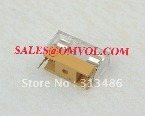
4) Calculate Fuse "Rating" : For DC Current, P=UxI.
You know P (Check in "User Manual"), Measure U (Ex: 20 V), Deduce I max.....
Only Install "Fast" Fuse.
NEVER Use "Delayed" Fuse...
5) Old Capacitors leaking is a common failure (In that case , this is the filtering Cap of Amp Power Supply. It can short circuit Power Supply once failed:
So, pay particular attention to Diodes Bridge (or Rectifier) and Power Regulating Transistor conditions as necessary.
6) Reinforce PCB "Power" tracks (mean allowing more current capacity) adding a "generous" tin lay on the tracks.
Hold On !!
Let us know
[ October 25, 2016, 12:06 PM: Message edited by: Phil Murat ]
Posted by Andrew Woodcock (Member # 3260) on October 25, 2016, 04:28 AM:
Or Ivy Watts (as spoken) as we affectionately remember the simple equation as.
As in I(current)xV (voltage) =Power (Watts) ...in a D.C. circuit.
Posted by Phil Murat (Member # 5148) on October 25, 2016, 08:10 AM:
Andrew, I have just realised the mnémonic !!!
5 Hours at least , to go to my brain.....
Posted by Paul Browning (Member # 2715) on October 25, 2016, 11:14 AM:
Hi Janice, send me your circuit diagrams, i'll see if I can find the components and where they might be in the projector. I have checked the spec on this machine and the internal speaker power is only 2 watts, so we are not looking for anything too big really, although it could intergrated into another chip. The cap leakage has damaged the tracks underneath, you will need to check this for continuity, the cap can be checked relatively easily when out. I wonder why the fuse was substituted, this is a safety feature and for a wire ??.
Posted by Andrew Woodcock (Member # 3260) on October 25, 2016, 11:21 AM:
As Paul highlights here, this machine does now appear to be well tampered with over the years and will take some extensive repairing to get fully operational again by the looks of things.
I just hope the board can still be serviceable in the future.
Removing a fuse circuit is a definite no no to begin with to whoever previously owned this machine
Posted by Janice Glesser (Member # 2758) on October 25, 2016, 02:53 PM:
@Phil...The leaky Cap looks like a good place to start. I'm going to order a new one. I already have a second fuse holder from when I installed a fuse on the top Speed Board PCB. The package I ordered came with two holders (with tops)
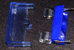
Once I get the cap removed it will be easier to see how much damage was done to the traces.
@Paul...PM me your email address. I'll send you the service manual.
@Andrew...The lack of fuses in this machine has been discussed and yes it's unfortunate. Someone else posted they had the same model machine and it too had no fuses. Mine doesn't appear to ever have had any fuses. So, I don't think this projector has been tampered with... I think it's a design flaw that was later corrected or maybe these were prototype machines...who knows.
Also from what I can see in the two layers of traces (one layer on each side of the board).I think it can be repaired separately without interfering with the other side. Let's hope so.
Posted by Andrew Woodcock (Member # 3260) on October 25, 2016, 03:16 PM:
Yes, i hope it can for you Janice.
Posted by Paul Browning (Member # 2715) on October 25, 2016, 03:46 PM:
PM SENT Janice.
Posted by Paul Browning (Member # 2715) on October 26, 2016, 12:05 PM:
Hi Janice, check components 647 on page 019 of your service manual, x 4 upright fixed ic's with heat sinks. If you get the numbers off these components we can google the numbers to check there use. The only other transistor is 622 on the same page, but there is only 1 of this item, but it does have a large heatsink, so there is some power going through it, could be a regulator though, a number will pinpoint its general use. The 647 might be npn and pnp complimentary, never seen them in that design before, maybe a lack of space dictated this ?. Your last picture are these in that picture, could be them, get the number off them please.
Posted by Janice Glesser (Member # 2758) on October 26, 2016, 04:58 PM:
Thanks Paul here is what I have on those components.
The 647 IC's were also illustrated on the PCB layout page F-14-0 (PDF Pg. 27). The parts list on the next page lists these as IC1-4, IC1-5, IC2-4, IC2-5 (although I don't see the IC2-5 in the illustration). All 4 are a TA-7217AP. The NTE equivalent is NTE1370 - Integrated Circuit 5.8W Car Radio Audio Power Amplifier, 10-Lead SIP Case, 18V Operating Supply Voltage.
DATA SHEET
http://www.weisd.com/store2/NTE1370.pdf
The 622 transistor is labeled T D635. The equivalent part is the NTE 261 TRANSISTOR NPN SILICON DARLINGTON 100V IC=5A TO-220 CASE COMP'L TO NTE262.
DATA SHEET
http://www.alliedelec.com/m/d/bda3e0ec856f41d1dfc4a8d80ae9359d.pdf
Posted by Paul Browning (Member # 2715) on October 27, 2016, 01:36 AM:
Hi Janice, so we are in the right area, but for it to go off completely both channels, even in a stereo amp quite unusual, not impossible though, given the problems you have had. I would first check you have power to the board, could be part of that cap problem we saw earlier, I would of thought there would be at least one fuse here, very odd.
Posted by Janice Glesser (Member # 2758) on October 27, 2016, 02:20 PM:
The plot thickens
Paul...By you identifying more potential problem areas... I took a closer look to the caps and traces around those power IC's. Well, it's not looking good. There appears to be more cap leakage and trace damage on both channels . Hopefully the IC's are ok. All I can do at this point is to attempt to replace all the leaking caps...repair the traces...and add a fuse to the circuit.
Damage between IC 1-4 and 1-5
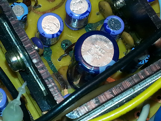
Damage between IC 2-4 and 2-5
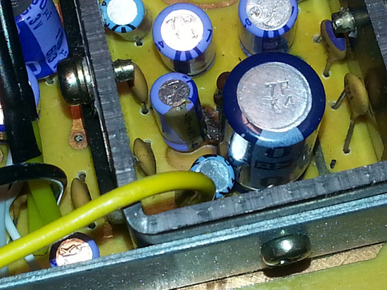
Luckily the components are at the accessible end of the PCB. So I don't think I'll have to remove the board. However the space is very tight next to the IC's. I'm trying to figure out how to remove the transformer to replace the big cap and fuse. I've contacted a couple members who have this projector for advice.
These repairs will take some precision and magnification tools as recommended by Phil. I'll also have to do a little more research on this type of trace repair. This will take awhile I'm sure.
Posted by Phil Murat (Member # 5148) on October 27, 2016, 02:39 PM:
Hi Janice,
You look to be on the right way......
Concerning addition of a fuse, my opinion is this not very urgent as that needs at first to find the better area to fit it (certainly between rectifier and Transformer Output).
Moreover, the protection is not 100% (unfortunatly, as sensible components like Transistors fail very very quickly. Anyway this is better than nothing)
Hold on Janice
Phil
Posted by Paul Browning (Member # 2715) on October 27, 2016, 02:53 PM:
Hi Janice, the caps are easy to do and relatively cheap, do them one at a time, but check those that look good too. the tracks are quite thin, not sure how these would be affected by the leaky caps, if could send them open circuit of high resistance ?. If you find that the amp chips have gone, be careful how you handle them, by this I mean physically. These can be zapped with static in the body, use something non conductive, plastic tweezers etc. Because you have no other functions other than the lamp circuit and forward projection, the power supply to other boards must be prime suspect, no power in no power out.
Posted by Janice Glesser (Member # 2758) on October 27, 2016, 07:51 PM:
I'm going to begin by removing the obvious leaking caps first. This will give me a better view of the condition of the traces. At first glance I see some oxidation (green) and corrosion from the electrolyte leakage. Since it doesn't appear there is any solder mask on the top side of the PCB I'm surprised not more of the traces haven't oxidized.
I still haven't gotten any further information on how to remove the transformer. I keep starring at the assembly diagram, but it doesn't seem to help. I'm going to PM Dogktor Frank to see if he knows
Posted by Janice Glesser (Member # 2758) on November 05, 2016, 12:42 AM:
I didn't hear back from Frank Arnstein...so just got out my screwdriver and gave it a go myself. Removing the transformer was easier than I thought it would be. I just removed the screws marked 1,2, & 3 and also removed the motor. I got the transformer detached and moved off to the side. Although I am having trouble removing the screw connected to the ground wire. I don't know why it's in so tight. If I can get that screw out it will be completely detached and much easier for me to work on the PCB. If I can't...then I might just cut the wire.
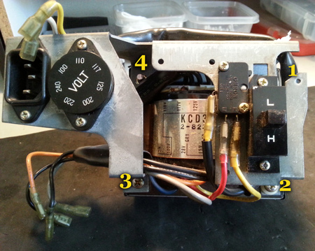
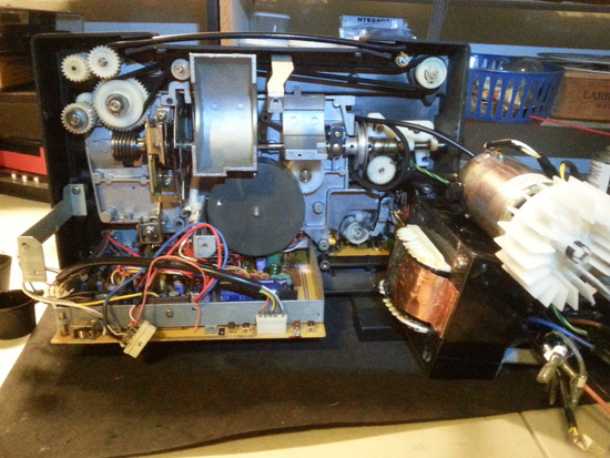
I got a magnifier and LED headband to help see the components and traces better on the PCB. I tried it out...and it really helped. Although my son said it looked like I was a Stormtrooper
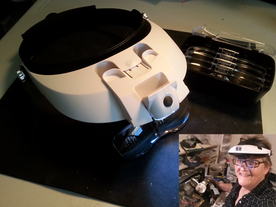
Posted by Janice Glesser (Member # 2758) on November 06, 2016, 03:57 PM:
I removed the big 4700uf 25V capacitor and cleaned the traces. However, there weren't any components connected to those traces. The capacitor metered good...but I ordered a new one anyway.
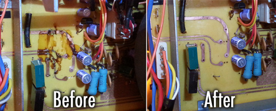
ALSO...What are these?
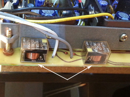
Posted by Andrew Woodcock (Member # 3260) on November 06, 2016, 04:11 PM:
Relays by the looks of things Janice.
Used to switch a large current circuit from a small one.
A small current energizes the coil in order to move the contacts to switch the large current circuit on or off.
If you want to test them, test the coil first for a circuit using your ohms range on your multimeter. You should see some resistance from the coil. Values vary dependent on number of turns and size of wire used etc etc.
With the correct D.C. voltage applied to the coil, you should see the contacts move forward and back again, as voltage to the coil is applied, then removed.
A spring returns the contacts to the normally open position.
The energized coil moves the contacts into the normally closed position.
These tend to fail more than anything else because of faulty contacts or because of faulty contacts movement mechanism.
This happens after many years of use and/ or if arcing has occurred over it's lifespan.
They are classed as a FCP (frequently changed part) in industry, just as bearings are, both being "consumable" components.
Posted by Mark Creighton (Member # 5276) on November 09, 2016, 01:04 PM:
Janice,
You will want to use a capacitor from a reliable manufacturer like Panasonic (Matshushita), Rubycon, Nichicon, United Chemicon, or Suncon (formerly Sanyo). You might also want to go with one with a higher voltage rating.
Mark
Posted by Janice Glesser (Member # 2758) on November 09, 2016, 02:22 PM:
Mark...I ordered a Nichinon 4700uf 25v capacitor from Ebay, but it won't be here for another week. I saw that Radio Shack has a 4700uf 35v...but don't know who makes these for Radio Shack. I'm tempted to go buy it...since it is a slightly higher voltage. But, I'm just not sure of the quality.
Posted by Mark Creighton (Member # 5276) on November 09, 2016, 02:31 PM:
Janice,
I would use the Nichicon. I have no idea who manufactures the Radio Shack capacitors.
Mark
Posted by Janice Glesser (Member # 2758) on November 09, 2016, 02:58 PM:
Mark...I checked again at what I ordered...it's a Panasonic GE capacitor, not a Nichinon. I've been ordering so many components lately it's hard to keep track. I guess I'll just wait.
Posted by Mark Creighton (Member # 5276) on November 09, 2016, 05:48 PM:
Janice,
The Panasonic should be good.
Mark
Posted by Steve Klare (Member # 12) on November 09, 2016, 07:04 PM:
Usually these components are rated for tens of thousands of hours of operation at temperatures most of the way to boiling!
So any decent commercial grade capacitor should do you just fine.
BTW: I'm a United Chemicon man myself! (For some reason the people I work for have always preferred them.)
Posted by Andrew Woodcock (Member # 3260) on November 09, 2016, 07:14 PM:
No worries Janice, you're welcome!
Go for the best rated,the difference in price is minimal...
105 degree rated and 5% close tolerance.
Reputable manufacturer, but the above is the more important.
Posted by Steve Klare (Member # 12) on November 09, 2016, 09:00 PM:
-but even if all you can find is 85C, don't lose any sleep over it. Unless the house is on fire that cap will never reach 185F.
Posted by Andrew Woodcock (Member # 3260) on November 10, 2016, 04:13 AM:
Just built to higher standard with greater head room, that's all Steve.
Factor of safety and all that.
We use an 8 tonne overhead crane in work, but it never sees more than 2t
Posted by Steve Klare (Member # 12) on November 10, 2016, 06:09 AM:
-not necessarily.
Very often you see the 85C part rated at 2X hours of Mean Time Between Failures and the 105C part rated only X hours. It's possible they are the exact same part with a different label.
My point is if Janice has an 85C part it's more than good enough. It's what the machine was probably built with in the first place since it's a consumer product.
The life of a capacitor in a super 8 projector is actually pretty plush: two hours a week year round is a lot and that's 100 hours a year. If you can only find a thousand hour part you are already good for 10 years. If that thousand hours is really only at like 40C it's probably more than 20 years.
20 years of this kind of service, everything else in the machine will be a pile of rubble! If nothing else the shelf life issue eventually gets them all regardless of the rated hours.
The systems I work on are intended to be up 24/7/365, so we would definitely go with the higher rated part: maybe save us having to get out of bed and go in at 3AM some winter night someday. (Comes with the job...)
-105C part if you can, 85C part: no anxiety!
Posted by Andrew Woodcock (Member # 3260) on November 10, 2016, 06:16 AM:
Yes fair points there, as you say all of these things ARE considered consumable items so for the amount of use, many give to these things, I am sure you're right.
I have to say though, I use my main projectors far more than two hours per week, so for the difference in price, I'd always plummet to fit the best available for my own needs.
There is after all, very little differences in prices typically.
As you say though, not everyone is using these things now to the extent I personally do, and no doubt, you do yourself Steve.
Posted by Steve Klare (Member # 12) on November 10, 2016, 06:29 AM:
I'd say an hour a week per machine would be a lot for me personally: I might only show one reel on a work night and I almost always run with two machines, so when it comes to even two 200 footers I do a changeover and the time is divided. I also rotate machines in and out of service and the guys on vacation can sit for weeks.
I'm guessing when you change a lamp, you can still remember the last time you changed it.
Posted by Andrew Woodcock (Member # 3260) on November 10, 2016, 07:07 AM:
Yes Steve. Every time. With the exception of my ST 1200 nowadays and my 938 gets very little run time per annum now.
I usually run a couple of features (two or three) and around 5 shorts per week.
I am a shift worker, so I do get plenty of time to view the films I have when I'm off and the wife is in work.
Plenty of time, yet still nowhere near enough for what is needed!
Posted by Janice Glesser (Member # 2758) on November 10, 2016, 04:07 PM:
Hi Andrew...in regards to the relays, thanks for the info. At this point I don't know if they are good or bad. I couldn't find these exact ice cube relays...but have located an equivalent if I need to replace.
1)I'll start replacing the big capacitor and adding the 6 amp fuse. Then put everything back together and test it.
2)If still no sound... then I'm going to replace the power amplifier transistor on the small speed board.
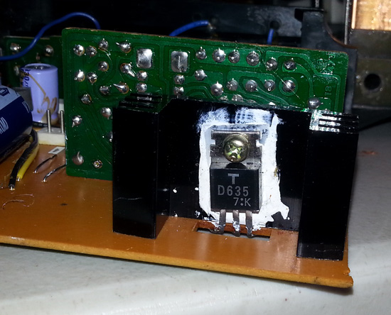
3) If still no sound...replace the two 470uf capacitors near the IC's.
4) If still no sound...test and possibly replace relays.
5) If still no sound...I don't want to go there
Posted by Janice Glesser (Member # 2758) on May 05, 2017, 11:45 AM:
UPDATE....No, I still haven't resolved the sound issue, but I haven't been working on the projector recently. If you venture back in this thread to my previous post you will see a list of my next steps. One of the to-do's in my list was to check the relays. I ran across a video on YouTube where this guy showed a nice little trick to test relays with a 9 volt battery.
https://youtu.be/uM8BO3pItec
I gave it a try and sure enough both relays were working. So I guess I can check relays off my list
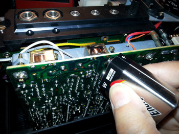
ALSO...I did complete #1 on the list. I replaced the capacitor and added a fuse holder and fuse. Still no sound
NEXT: #2 - Replace power transistor
[ May 05, 2017, 05:03 PM: Message edited by: Janice Glesser ]
Posted by Janice Glesser (Member # 2758) on October 02, 2017, 08:12 PM:
Replaced the transistor on the power board today. Unfortunately this component was not the problem and still complete silence.
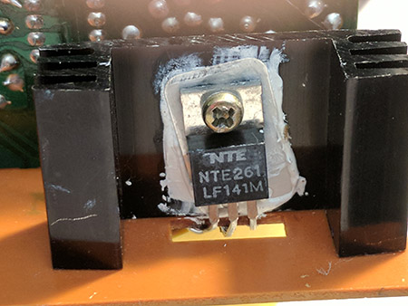
This is what I know:
1) Power is getting to the motor and it runs great.
2) Power is getting to the lamp
I do not know if power is getting to the sound board or amp.
How can I test this?
Posted by Graham Ritchie (Member # 559) on October 02, 2017, 09:42 PM:
Janice I am certainly not an expert in amps...but my guess would be if you can hear hum from the speaker when cranking the volume to full running the motor as well then the amp is working...no hum.. no amp
Posted by Janice Glesser (Member # 2758) on October 03, 2017, 12:37 AM:
Well Graham then I know one more thing...
There's no hum...so no amp
It's sad to see such a nice stereo projector so crippled. I just don't know enough to intelligently troubleshoot where the disconnect is located. Even having all the circuit designs hasn't been much help.
I know something blew when I touched a metal bar by mistake. Poof!... and it went silent.
Posted by Graham Ritchie (Member # 559) on October 03, 2017, 02:07 AM:
Hopefully someone will come to your rescue Janice.
Just thinking, is the pre-amp still ok? If the main amp is gone and the pre-amp is ok then by pass it to a aux out, then run the leads to a external amp..or get one of those amp kits you can buy and build a new one. Another thought an old cassette tape deck scrap it and take the pre-amp out of it and wire it to projector sound head..to a aux out...external amp
I think you will get there in the end, it might even be nothing more than a blown transistor..but I think you need to take it to an electrical repair to fix it.
Anyway food for thought...
Posted by Janice Glesser (Member # 2758) on October 07, 2017, 11:23 AM:
Just when I think the plot points in this novel (actually this is a documentary) have gone dry... a small spark of hope emerges
Graham... you got me brainstorming again that this might be as simple as a blown transistor. I had been spending hours and days trying to learn about amplifiers and the components. However, I decided last night to go back and re-read this thread. I don't know how I missed it...but Pete Richards had suggested replacing the green Toshiba 1B2Z1 rectifier. In the same area as that rectifier I had already replaced a large capacitor and added a fuse. I never followed up on identifying and replacing that rectifier. I guess at the time I didn't know what that green thing was (: . Anyway... I also located an old thread from 2006 http://8mmforum.film-tech.com/cgi-bin/ubb/ultimatebb.cgi?ubb=get_topic;f=1;t=001730
Here Jan Bister had almost the identical problems with his Sankyo 800. He mentions replacing that same rectifier and it restored the sound to his projector.
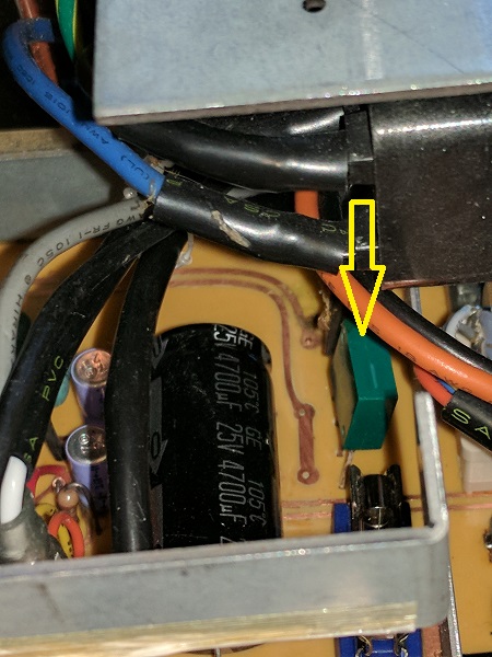
After this epiphany at 1 a.m. in the morning... I found the part on Ebay. It should arrive by next Friday.
Crossing fingers....Stay tuned for this next chapter
[ October 07, 2017, 08:55 PM: Message edited by: Janice Glesser ]
Posted by Janice Glesser (Member # 2758) on October 17, 2017, 06:16 PM:
I replaced the Green Rectifier yesterday...but unfortunately "no joy." I've now ordered a replacement for the black rectifier that sits right next to the green one. It measures correctly with the ohm meter...but Pete Richards says it may not work under a load.
Granted I'm disappointed...but I did learn something about a rectifier stack and it's polarity. Unlike a bridge rectifier that has 4 terminals...a rectifier stack only has 3 with the center terminal being common... positive or negative. On the Sankyo 800...the green rectifier has a positive common...where the black one has a negative common.
The new black rectifier is coming from the UK and will take a couple of weeks. I'll report back then.
Posted by Janice Glesser (Member # 2758) on November 05, 2017, 07:03 PM:
Got the replacement black rectifier installed... but still complete silence
Graham...How do I test to see if the pre-amp is working?
Posted by Thomas Knappstein (Member # 6134) on November 07, 2017, 11:44 AM:
I dont have this Sankyo 800 machine but the same Rectifiers are in my Elmo GS 1200. The green one and the black one together make a normal Bridge Rectifier because there are two Diodes in the Green one and two diodes in the black one.
If you have changed both of them and canged the big Capacietor there must be a Voltage about 15-20Volts measuring on the Capacitor. If it is not check the AC Voltage on the Transformer. I dont think that the Preamp is defektive. I think if it´s not the Power Supply it could be the End Transistors ore Hybrid Part. Because If the Preamp is defektive and enything else is ok than you must here a Hum in the Speakers but no Sound of the Film. And you say that there is no Hum so it could be an Idea.
Posted by Janice Glesser (Member # 2758) on November 07, 2017, 07:21 PM:
Hi Thomas...I greatly appreciate your thoughts. I haven't checked the voltages since I got the motor running on this machine. I'm always hesitant to test with the AC plugged in...that's how I blew it in the first place.
Posted by Thomas Knappstein (Member # 6134) on November 07, 2017, 10:24 PM:
I hope you will fix this Problem and it will run once a Day.
Posted by Janice Glesser (Member # 2758) on January 12, 2019, 02:22 PM:
It's been a little over a year since I updated this thread and I'm happy to announce that I finally have a fully working Sankyo Stereo 800. Here is how it went:
I was able to buy a second "non-working" Sankyo 800 for a very low price. The sound was working on this projector, but the motor wasn't running.
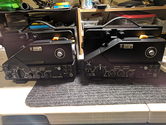
I pulled out the power board and discovered that like the first projector...the bridge rectifier was cracked...
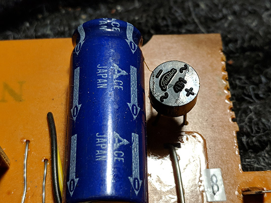
...and the PCB trace was burnt.
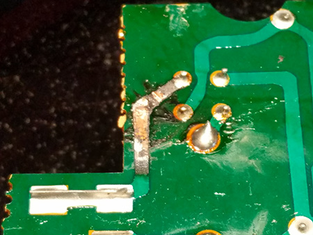
In hopes that with the repairs I had already done to the power board on the first projector would be suffient... I decided to switch out the boards.
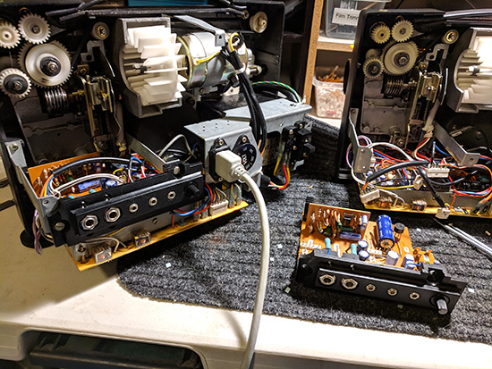
When possible I try and number the connectors and the wires so I don't have to guess later on when reconnecting.
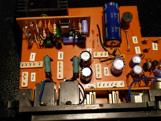
SUCCESS!!!! The projector motor started right up...the arm spindles were turning and the sound lights all turned on.
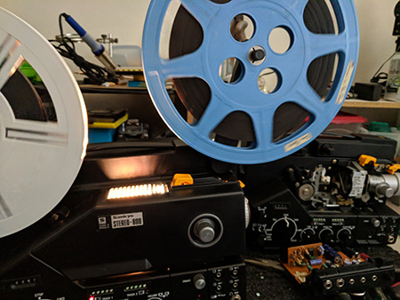
I'm happy to have a working projector, but feel bad I couldn't get the sound working on the original machine.
Thanks everyone who contributed to this thread. It has been a wonderful learning experience and I hope others can benefit from the information.
[ January 12, 2019, 06:15 PM: Message edited by: Janice Glesser ]
Posted by James N. Savage 3 (Member # 83) on January 12, 2019, 07:15 PM:
Thanks so much for the update Janice! So glad to get a happy ending on your Sankyo project. Hope you will enjoy your machine for many years as I have too.
James
Posted by Janice Glesser (Member # 2758) on January 14, 2019, 09:52 AM:
I'm glad to finally wrap up this project James and thanks for your interest. Sankyo has made some great projectors and I've owned several models. The Sankyo Stereo 800 is the top-of-the-line and a pleasure to run.
Visit www.film-tech.com for free equipment manual downloads. Copyright 2003-2019 Film-Tech Cinema Systems LLC

UBB.classicTM
6.3.1.2