This is topic Bauer T10 problem in forum 8mm Forum at 8mm Forum.
To visit this topic, use this URL:
https://8mmforum.film-tech.com/cgi-bin/ubb/ultimatebb.cgi?ubb=get_topic;f=1;t=011479
Posted by Barry Fritz (Member # 1865) on May 10, 2017, 12:37 PM:
I just picked up a T60 from a Thrift store auction. Lights and motor work fine in reverse, but only the lights work in forward....no motor at all. The switch is mechanical and seems to work ok. Any thoughts or suggestions?
[ May 11, 2017, 01:13 PM: Message edited by: Barry Fritz ]
Posted by Andrew Woodcock (Member # 3260) on May 10, 2017, 12:41 PM:
Sounds like a micro switch Barry, either not quite contacting or broken /bent lever or roller etc
Bauer machines often have a camshaft off the main control knob.
You can check the functionality of each of the main control knob positions by placing a multimeter across the terminals of each of the resulting micro switches in resistance or continuity mode to see if one isn't doing its job quite right.
Leave the mains lead out of the machine while doing this task.
No power required or indeed necessary.
Having just seen a photo though, these are very old Bauer designed machines so it may very well not have a camshaft or any micro switches. I'd have to see inside it to know for sure how it gets its power from the control knob on a machine as old as this is. (1950's I think?)
[ May 10, 2017, 02:19 PM: Message edited by: Andrew Woodcock ]
Posted by Steve Klare (Member # 12) on May 10, 2017, 12:45 PM:
If it's anything like the machines I know. There is a switch running to each motor terminal. These choose +DC or -DC so that the motor can be connected one polarity or the other and go in the direction you need it to go.
These are activated by cams on the shaft the control knob turns.
To me it sounds like one of yours has a bad contact and your motor voltage is going no further.
I'm sure this one is worth the effort, but these are buried deep in the bowels of the machine. I'm not saying they are hard to replace, but once you succeed you really deserve a beer!
Posted by Andrew Woodcock (Member # 3260) on May 10, 2017, 02:22 PM:
To get to the camshaft on any, there is always a fair bit of dismantling and cable detachment / labelling on any I've worked on in this area.
It's a lot easier and quicker when spade connectors are fitted.
Posted by Maurice Leakey (Member # 916) on May 10, 2017, 03:06 PM:
Van Eck's site has some pictures of this standard 8 projector which may help as there is a shot of the interior. Click on T10R.
https://www.van-eck.net/itable.php?lang=nl&size=0&cat=film&merk=13&type=T10 R
Posted by Barry Fritz (Member # 1865) on May 10, 2017, 03:15 PM:
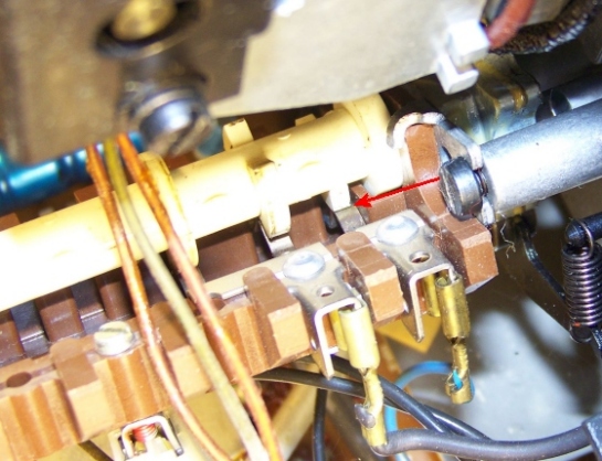
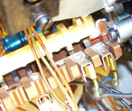
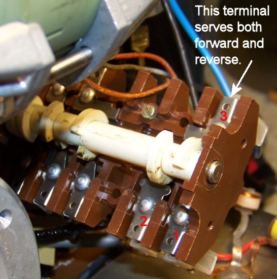
Here are pics of the camshaft part of the switch. The arrow points to what I believe is the cam for the forward motor movement. Odd thing is, the terminals here indicate continuity when the cam is not pressing down on the metal tab. With the cam pressing it down, there is no continuity. That is the opposite of all the other terminals with cams.
Posted by Andrew Woodcock (Member # 3260) on May 10, 2017, 03:30 PM:
Barry, you should be able to tell by observing the switch position whilst also looking at the various cam lobes, how this camshaft was intended to switch.
Are all the lobes logical in their placement?
Does it make sense in other words that the lobe is moving each section of the mechanism to make the desired connection in relationship with main switch knobs marked positions?
If they are all in the same logical position, the only possibility could be that two wires have been switched around maybe (put back wrong) NO / NC for example, or the switch mechanism is faulty in some way or one of the cables themselves is OC but this is unlikely even if not impossible.
(Nothing ever is!)
The photographs don't really allow us to see the actual switch mechanism unfortunately only the cam lobes and some of the contacts / terminals.
Does this camshaft and switching mechanism reverse the polarity to the motor as Steve suggested?
You might have to "ring" the circuit from each terminal pictured to the actual motor terminals to fully understand what is happening in this circuit without any drawings.
This when compared to the cam lobe position in each case added to the actual main control knob position and markings, should then begin to make some sense to you as to what is allowing the circuit to fail.
Posted by Steve Klare (Member # 12) on May 10, 2017, 03:34 PM:
He has much better access than usual.
-The last time I did one of these, I swear I briefly saw the Ark of the Covenant!
I'm guessing there are two switches to the motor. One chooses the connection for each motor lead. If you choose forward, each will choose one power supply lead or the other. If you choose reverse, each will chose the opposite.
When you look with with an ohmmeter, the good switch will make a choice either way, but the bad one will only make a choice in reverse.
Posted by Barry Fritz (Member # 1865) on May 10, 2017, 03:45 PM:
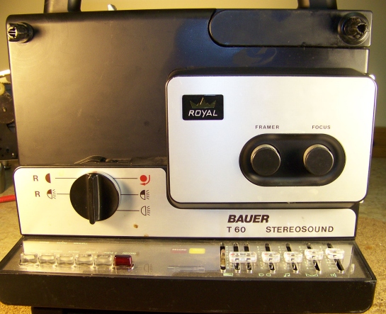
First off, I don't know what I was thinking when I called this thing a T10. It is a T60. Here are some more pics. Andrew, it appears to me that the cams are working as they should. When switched, lights and reverse work. Forward has three positions, Thread, half light and full light. Motor does not run in any of these selections.
Posted by Andrew Woodcock (Member # 3260) on May 10, 2017, 03:48 PM:
Ah...different animal altogether then! 😂
Does the lamp illuminate in each mode?
In other words those circuits are good?
Sorry just read the beginning again, and indeed they do!
Just forward direction then...
My drawings and service manuals are in my case of the T610 currently at the lock up. I will have a look on my pc to see if I have any electrical drawings for this model on my main pc but I know they are not covered in the T610 / 525 service manual although this part of the set up may well be almost identical. The motor is very different though.
The layout in general is quite similar to what I am familiar with seeing on the T610's.
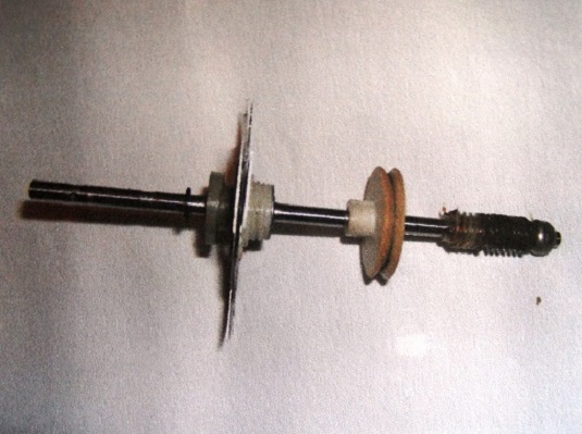
Posted by Barry Fritz (Member # 1865) on May 10, 2017, 03:51 PM:
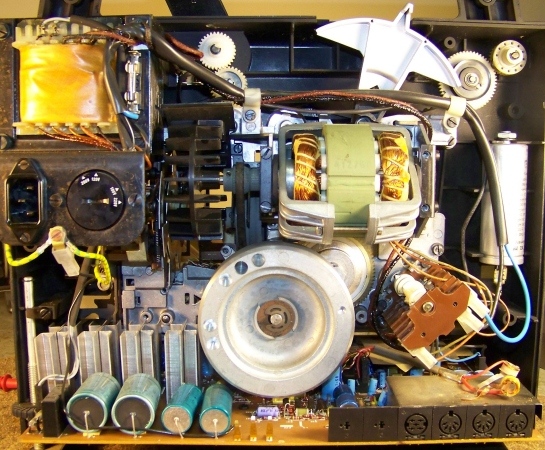
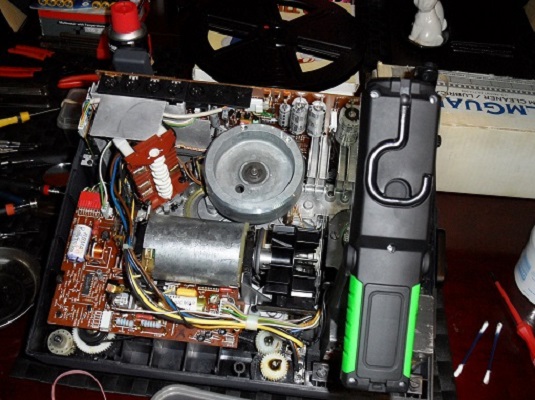
Yes. You can see the switch cam mechanism and terminal in the lower right. I think that entire mechanism may just slide off the knob shaft. I may need to try that to see if something is amiss with the forward motor terminal. Connecting the terminals there with a jumper wire should make the motor go, shouldn't it?
Posted by Steve Klare (Member # 12) on May 10, 2017, 03:54 PM:
As thrift store machines go, this is quite a find!
I've never seen a machine there I'd use for more than a doorstop!
Posted by Andrew Woodcock (Member # 3260) on May 10, 2017, 03:58 PM:
Straight away Barry, I can see now that this model has a large mechanical lever on top of it.
Is this the 18fps / 24fps lever? (White)
I'm sure this is an a.c. motor which would then explain why the white lever is needed.
If it an a.c. motor the forward reverse direction changes will be mechanical not electrical.
The motor rotational direction should never change in forwards or reverse, only the gearing through a mechanical arrangement.
I've just looked on S8 database at this model, but there is no mention of the motor type there sadly, but it appears to be an a.c. motor from your photo and that large white lever on top.
Posted by Barry Fritz (Member # 1865) on May 10, 2017, 04:00 PM:
Yes Andrew. It moves the belt that can be seen next to the fan.
Steve, If I can't get this working, that may be all it is good for!
Posted by David Roberts (Member # 197) on May 10, 2017, 04:08 PM:
yes Andrew,its the speed change lever.
have just been using my t60,great machine.
Posted by Andrew Woodcock (Member # 3260) on May 10, 2017, 04:08 PM:
All it now points to Barry, is somehow the voltage that is present on the motor terminals in reverse, isn't present in forwards projection mode unless of course the motor is seizing for whatever reason when trying to drive the gearing arrangement in the forwards direction.
The next stage, first off, is to very carefully test whether you have an a.c. voltage on the motor terminals in the forwards direction like you do in the reverse direction.
Only if you're confident on working on this machine live though Barry and certainly keep well away from the transformer until detached from the mains again.
Thanks btw David for confirming the lever.
Another test Barry, would be to slip off the motor drive belt temporarily just to see if the issue is an electrical one or a mechanical one. The motor should turn easily then when your main control knob is placed in forwards projection mode or reverse projection mode as it does already but only in reverse with the belt fitted, if the problem is a mechanical one.
Posted by David Roberts (Member # 197) on May 10, 2017, 04:09 PM:
Barry,this is a great machine so I hope you can sort out a fix.
Posted by Andrew Woodcock (Member # 3260) on May 10, 2017, 04:16 PM:
Just noticed the large capacitor for the motor also which is a dead giveaway that its an a.c. motor also.
David, if Barry gets nowhere with this tonight, (it's becoming late here already for a school night!😂), could you possibly confirm tomorrow on your model that the motor shaft itself moves in the same rotational direction in both forwards and reverse please?
Just the motor shaft itself please David.
This is typically how things are on these size of motors used in these applications, but there is a very slight possibility it could rotate in both directions depending on run and start winding configurations if a switch was fitted to it internally.
(Highly unlikely though and certainly doesn't appear to be this type)
We very much first need to establish what enables this type of machine to switch from forwards to reverse direction from the actual main control knob. It is not clear from any of the photographs so far, whether the knob also moves a series of mechanical linkages like on the T610. This can only be seen from the front of the machine with the cover removed.
Even then, on a 525 /610 these linkages do not control the motor direction because it has a D.C. motor, but on this one, they may I'm guessing, through a series of gears. (Again unclear just from these photographs alone. The flywheel doesn't help either for seeing what happens to the main drive belt and beyond. It appears to go down to a worm gear I'd guess).
Posted by David Roberts (Member # 197) on May 11, 2017, 05:59 AM:
Andrew,
have checked my t60,and the motor runs both clockwise and anti clockwise,depending on forward or reverse projection.
Posted by Andrew Woodcock (Member # 3260) on May 11, 2017, 06:32 AM:
Thanks David. That makes it very different then to other machines like a S938 for example, in how it works.
On these, the motor runs constantly in one direction as soon as it is powered up. The drive chain then just changes direction mechanically.
Same on an ST 1200 i think from memory though its been a while since i last worked on one of those.
I think Barrys best move then first would be to verify that the motor still does not turn with the drive belt taken off the motor pulley, then it would come back to requiring the drawings for one of these to see what actually switches the power supply to the motor in forward and reverse. Might just be the camshaft and connections again, might be more to it??
Anyone have the schematics for one of these plesse?
Posted by David Roberts (Member # 197) on May 11, 2017, 07:04 AM:
Andrew,
I also have the 520 duoplay model which is a later model,that has the same speed change lever,so would think it has the same motor as t60.
this probably doesn't help much,except someone may have a circuit for the 520.
Posted by Andrew Woodcock (Member # 3260) on May 11, 2017, 09:03 AM:
Thanks David. I could do with seeing drawings for either the T60 or the 520 to gain a better understanding of how these are switching rotation.
How many cables enter the motor David or Barry?
David are you able to measure the voltages present on each cable end from your motor in forwards and reverse?
This would certainly help in understanding what Barrys issue with his may be just in fwd mode.
Posted by Barry Fritz (Member # 1865) on May 11, 2017, 09:20 AM:
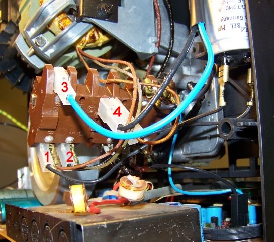
Hey Guys: Andrew, the motor has three wires. One green and two orangish. I did a bit of testing. I have determined that the terminal 1 is for Forward, and terminal 2 is for Reverse. Each terminal has a wire from the motor and a black wire running to the capacitor. Terminal three is double, and serves terminals 1 and 2. It has a blue wire that runs up to the transformer. Number 4 is a coupling that has an orange wire from the motor and a black wire that runs up to a terminal on the back of the dial where you select the voltaqe. Thus, I believe it is the power to the motor. Voltage readings for terminals are as follows:
Terminal 1: Off is 121.8V On is 200.7V
Terminal 2: Off is 121.8V On is 121.8V
I cannot figure out why the 200.7V reading is there.
UPDATE: I think I found the problem. First off, when the cam turns down into the assembly, that disconnects the circuit. It pushes down a small metal tab that is the connector. Turning the cam up releases the little tab and it touches the terminal across from it. It seems to be working on the Forward terminal, but I can't see if the tab is actually touching. So, I took a jumper wire and fixed it to terminal three and touched the other end to terminal 1. Voila, motor spins nicely. Now I have to see if I can discover why the connection is faulty. The tab looks fine but it is supposed to touch the underside of the 1 terminal, and apparently it isn't. Some bending may be in order.
[ May 11, 2017, 12:37 PM: Message edited by: Barry Fritz ]
Posted by Andrew Woodcock (Member # 3260) on May 11, 2017, 02:12 PM:
Well done Barry. Sorry I have been in work all day and can only post sporadically.
I did see your latest post in the afternoon here, but I was trying to understand how you could be seeing 200v at one of the terminals in your part of the world.
That part in all this, still remains a mystery.
As you say just a bit of slight bending etc, to make better contact as a connection and hopefully you are up and running!
Well done once again and some good learning here for everyone who has never had any experience with this particular machine.
Myself very much included! ![[Smile]](smile.gif)
Posted by Barry Fritz (Member # 1865) on May 11, 2017, 03:01 PM:
Well guys, I have it working correctly! I have a tool with a little hook on the end, and by reaching in and pulling up on the tab slightly, I got it working! Nice quiet machine. Ran some leader through it and it threaded just fine. Drive belt is cracked but working for now. Hope I never have to change it..it looks difficult. Now I just need to find a Manual for it. Thanks guys.
Posted by David Roberts (Member # 197) on May 11, 2017, 03:54 PM:
yes well done Barry. I have a t60,520 and 502 and these are the only projectors I now have.They are so quiet and kind to film,plus ive never had one not lace up first time.
Posted by Barry Fritz (Member # 1865) on May 11, 2017, 04:18 PM:
Thanks David. Yes, it seems that it is a very nice machine. The leader I used was on a small roll and pretty curled up. It fed through very nicely and is very quiet. I thought that when threaded it, I would need to press down on the small silver lever on the front of the machine below the lens, but not so. What is the purpose of that lever?
Posted by Andrew Woodcock (Member # 3260) on May 11, 2017, 04:21 PM:
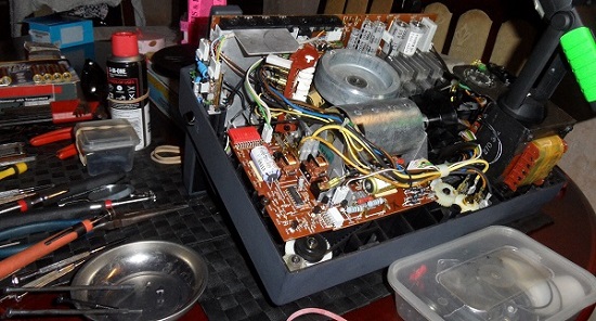
Barry, I don't know for sure having never owned or worked on one of these, but just looking at your full picture here of the inside of your machine, the drive belt does appear far easier to remove than on a 610 for example.
The reason being, you don't appear to have a shutter shaft that runs almost the full length of the machine on this one which is the big issue in carrying out this job on the 610 /525 etc while also trying to safeguard the critical cam position and endfloat on these.
Go and enjoy that Beer now Barry that Steve spoke of at the beginning of all of this. You deserve it pal! ![[Wink]](wink.gif)
I think the lever may be the same as the one fitted on these btw.
If it is, it is there to eliminate any jitter you experience at the gate after threading and placing in run. To be honest though, you should never really need to use it unless you ever begin to experience claw problems. Hopefully you won't Barry.
Keep your leaders dovetailed, you should never have any issues threading film with this design used for these machines.
Posted by Barry Fritz (Member # 1865) on May 11, 2017, 04:41 PM:
Thanks Andrew. I think you are correct about that lever. It's sort of like a loop restorer. I treated the belt with rubber roller restorer and hopefully that my prolong its' life. I do agree that the belt on mine may be a bit easier to replace than on the machine you show. Are belts readily available for them?
Posted by Andrew Woodcock (Member # 3260) on May 11, 2017, 05:09 PM:
I don't know of the exact size of yours on the T60 Barry, but the original square profiled ones are no longer available but there are plenty of round profiled decent replacement belts about.
Square would be nice to match the exact profile of the Vee on the pulleys, but round do suffice I have found.
I have no idea in the USA where you would source a belt, but here in Europe people like Van Eck or FFR supply them for my own machines and most likely this one also.
Posted by Barry Fritz (Member # 1865) on May 11, 2017, 07:08 PM:
Andrew, it looks like Van Eck has them.
I loaded in a sound film just now and get nothing. Seems there is some work to do. Not a big deal, I like playing around with them now that most of my 16mm projectors are gone.
What the heck are these two little coils on the T60 for?
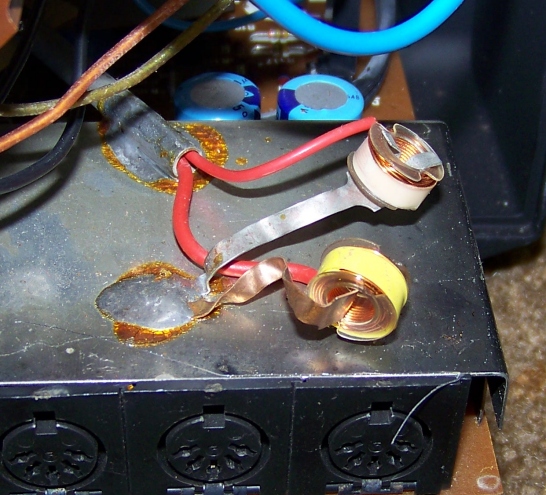
Posted by Paul Adsett (Member # 25) on May 11, 2017, 07:11 PM:
They look like hum bucking coils Barry.
Posted by Barry Fritz (Member # 1865) on May 11, 2017, 08:20 PM:
Hmm. Thought humbuckers pertained to guitars. Interesting. Thanks Paul.
Posted by Andrew Woodcock (Member # 3260) on May 11, 2017, 11:45 PM:
That's a shame to hear about Barry, regarding the sound.
Still, that's probably the reason why it was where it was I suppose.
As you say Barry, a nice little project to play around with anyhow and hopefully, fully working again in the none too distant future.
To have no sound at all might be a little better to diagnose than if you had intermittent or one channel faults perhaps?
Good luck with it anyhow and perhaps start by giving it an external input to see if the pre amp has any life in it?
Also just try working those switches beneath the main control knob a few dozen times or so with some contact cleaner also if you have any. It may well have been many many years since any have been previously used.
As you have just found out and also just by looking at your the images of this machine, the evidence all suggests their may be little actually wrong with this machine. It appears very clean and well looked after, but it may have many oxidized contacts from lack of use of slight wear to contact springs etc etc.
On the T610, it even uses poorly designed contact leaf springs to take the connection of the amplifier outputs onto the speaker wiring in the rear cover.
If this is the same, here is another area to give your attention to.
[ May 12, 2017, 03:04 PM: Message edited by: Andrew Woodcock ]
Posted by David Roberts (Member # 197) on May 12, 2017, 02:44 AM:
Barry,
the silver lever is a loop restorer,should you ever have a bad splice or damaged film go through and cause a loss of loop.
As Andrew says,the coils are to reduce hum,the only downside to this machine is a slightly higher level of hum on playback. This has been reduced on mine by using a 4 ohm ext. speaker,which the amplifier seems to prefer.
good luck with the sound,it really is worth getting this machine going.
Posted by Andrew Woodcock (Member # 3260) on May 12, 2017, 05:28 AM:
Just for clarity, it was Paul who said quite rightly that the coils are hum bucking coils, not myself. My Machines did away with these so it isnt something i have seen written down in any of my own parts lists.
Im sure Paul is spot on though in his assessment of what function these coils carry out. ☺
I believe these coils can be positioned or angled to any position to find optimum position in subduing the hum from the amp.
Posted by Barry Fritz (Member # 1865) on May 12, 2017, 08:56 AM:
Thanks for the info guys. I'll be checking to speaker contacts as mine are the same as yours, Andrew. Also input from my old cassette player to see if there will be any sound.
Posted by Andrew Woodcock (Member # 3260) on May 12, 2017, 11:49 AM:
And work those switches Barry.
Beyond that its power to the board, fuse, large caps etc etc
Its slightly encouraging though having no sound at all at this stage. Might be something very obvious.
Dont you even get any hum through any speakers with the machine in idle and volume turned right uo?
Posted by Barry Fritz (Member # 1865) on May 12, 2017, 02:12 PM:
Just got back from playing a round of golf. It is 71 degrees, sunny wih no wind. Beautiful! Andrew, there is no sound at all. I will try checking the leaf spring speaker contacts and will work the controls. I know based on my experince with older 16mm projectors, corrosion can be a significant problem.
Posted by Barry Fritz (Member # 1865) on May 12, 2017, 08:14 PM:
Can't hook up external sound source to check preamp. The sockets are odd multi pin gizmos. Pressed the r
Record button and it lit up as did the VU meter. That's all to report for now.
Posted by David Donaldson (Member # 3858) on May 12, 2017, 10:18 PM:
A nice story of collaborative thinking. Sprang to my notice because I have a T10R. It runs nicely. A lamp for it cost more than the projector, so I hope when I need it that the lamp too will function.
Posted by Andrew Woodcock (Member # 3260) on May 13, 2017, 04:35 AM:
Yes Barry, unfortunately you will need to source some 5 pin DIN connecting leads going out to 2 RCA Phono Sockets/ plugs or 2x 3.5mm Mono Jacks before you will be able to fully test the pre -amplifier circuit with an external source.
Id like to think they are still readily available though in the U.S. From places like Radio Shack (if it still exists there?).
I personally, wouldn't expect corrosion to be an issue on one of these, but for sure oxidation of contacts etc,may well be.
As also might be poor connection in some switches and contacts.
It's also quite common on these styled amplifiers, to require a change out of the duo large capacitors in the amplifiers power amp circuits on these and sometimes the smaller two at the side of these.
If they haven't been used for years, they completely dry out in many cases making them useless.
On my own machine, these can be seen in above photographs in the top right hand side corner of the machine in the manner I have photographed it in, above the capstan flywheel.
Posted by Barry Fritz (Member # 1865) on May 13, 2017, 11:32 AM:
I'll chck those caps. On the older amps in the16mm projectors I worked on, the electrolytic caps commonly failed, as did the other paper/ wax caps. However , I found many that were 60 years old and still good. There are still a couple of Radio Shack stores open so I can check them.
UPDATE!! Fixed it! It was those spring steel speaker connectors Andrew mentioned previously. I had put the back on because it needs to be on to check the sound, but had not removed it until now. I bent the connectors down, and Viola! Sound! I have B&H, Elmo, Eumig, Bolex and Sankyo projectors, and I must say this Bauer is the quietest of them all.
Posted by Andrew Woodcock (Member # 3260) on May 14, 2017, 02:56 AM:
Congratulations to you once again Barry in successfully restoring your new machine. Having never seen a T60 in run, I have no idea just how quiet these projectors are but if it's anything like a T610 with a decent cam and follower, they are near silent by the time you are playing your soundtracks at even just audible levels.
I am still yet to find a quieter and smoother running machine than a good one of these. They are an absolute delight to use.
Happy Screenings Barry, now with Stereophonic sound and not a great deal of any other! ![[Big Grin]](biggrin.gif)
Visit www.film-tech.com for free equipment manual downloads. Copyright 2003-2019 Film-Tech Cinema Systems LLC

UBB.classicTM
6.3.1.2