This is topic Broke Sankyo 500 in forum 8mm Forum at 8mm Forum.
To visit this topic, use this URL:
https://8mmforum.film-tech.com/cgi-bin/ubb/ultimatebb.cgi?ubb=get_topic;f=1;t=011561
Posted by Peter Gilabert (Member # 5948) on June 17, 2017, 10:52 AM:
I took out my old Sankyo 500 projector and after plugging it in it began to emit a nasty white smoke near the power outlet.
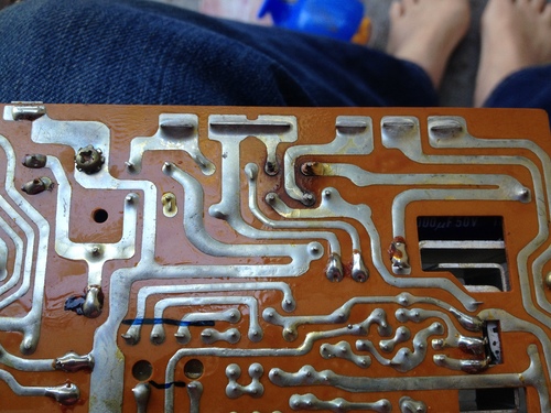
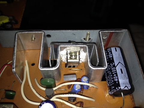
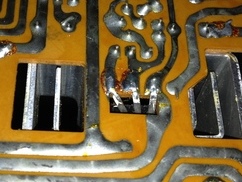
It makes a hum sound but that's it. Opened it up and everything looks good except the circuit board has a burn on the back:
Now on the other side sits a small black cylinder held up by four thin wires. I'm guessing this might be a capacitor? It's cracked, so I know it's bad,( in the Middle of this pic):
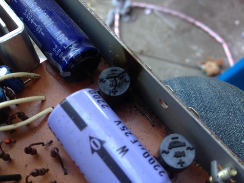
So, the capacitor or whatever it is says 4B1 Toshiba on top and on the side says:
1B 8 C
I've researched how to read capacitor codes and I'm just going in circles, I've been to the Mouser Electronics website and they want more info then I can fathom- to order a new one.
I have a soldering iron and i'm game to fix this- Anyone have any clue how to solve this mystery?
Like What exactly is this 40 year old part? And how do I define the readings on it?
The only thing I might guess is the letter B means 0.1pF and and 1B 8 means 100000000pF? But Mouser wants tons more info I don't have a clue about.
Yikes! Any Help is appreciated!
Thanks! -Peter
Posted by Phil Murat (Member # 5148) on June 17, 2017, 11:54 AM:
Hello Peter,
I can see by the 2nd picture, 1 black cylinder cracked is Bridge Rectifier.
It seems there are 2 bridge rectifiers.
Pay attention to choose Rectifiers with working Amp higher than Fuse rate (Ex: Fuse 3A, Brifge 6A....)
I suggest you to replace both of them with associated capacitors.
Phil
Posted by Janice Glesser (Member # 2758) on June 17, 2017, 01:52 PM:
Hi Peter and Welcome! I got a little feeling of DejaVu in reading your description of what happened with your Sanyko 500. I had a similar experience with a Sankyo Stereo 800. I had to repair burnt traces on the PCB as well as replacing the Bridge Rectifier and Capacitor. My board didn't even have a fuse so I had to install one. It might be helpful to look an my thread on these repairs. However I'll warn you it is kind of a mini novel ... but there are some good pics ![[Smile]](smile.gif)
http://8mmforum.film-tech.com/cgi-bin/ubb/ultimatebb.cgi?ubb=get_topic;f=1;t=008244
I don't know if the Bridge Rectifier I used is the same as on your board...but I used a NTE5304 that I bought at Fry's. The good news is that after these repairs I actually got the projector running again, however in the process I had blown something in the sound system and I'm still working on that.
Posted by Peter Gilabert (Member # 5948) on June 17, 2017, 07:20 PM:
Phil thanks for your input.
Janice thanks for the novel-
adventure story about your Sankyo. I read it it with great interest.
I did the transformer test as suggested by Pete in Australia- on mine.
Yeah, nothing.
But, like yours, the motor works.
I don't suppose anyone has a spare transformer for a Sankyo 500 out there?
If so, I could start a "Son of Sankyo" thread, otherwise it'll be called "Sankyo- D.O.A." ![[Frown]](frown.gif)
Posted by Janice Glesser (Member # 2758) on June 17, 2017, 11:20 PM:
It's too bad your projector isn't also a Sankyo 800. At the time I bought a second transformer, because I thought the one in the projector was bad. However that turned out to not be the case so I still have the transformer
Posted by Peter Gilabert (Member # 5948) on June 18, 2017, 08:37 AM:
@ Janice-
So there may be hope that since I did the same "test" for power on my transformer as you did on yours- that mine may be ok after all then?
That would be great- the funny thing is , it looks newer than anything else in the projector...
I don't want to spend too much more wasted effort fixing the board for nothing, but hmmm...
Posted by Janice Glesser (Member # 2758) on June 18, 2017, 02:30 PM:
Peter...I'd say if you are up to it... repair the burnt traces...replace the Bridge Rectifier...the two larger caps and if yours has a fuse replace that also. There's a chance you can get it up and running again. The cost will be more in your time rather than the expense of the parts.
Posted by Peter Gilabert (Member # 5948) on June 18, 2017, 10:56 PM:
So, I have good news and bad news:
Today I replaced the bridge rectifier and the capacitor that's connected to it, put the projector mostly back together and...it "turned on", meaning the indicator light came on AND no scary smelling white smoke!
Alas, the motor doesn't turn over! The same motor that DOES work when I did the 'Pete from Australia' test when I hooked up a 9 volt battery directly to the motor wires! So it works and it doesn't work at the same time, heh...
The lamp doesn't light up but that doesn't worry me- it's forty years old and I'm sure needs to be replaced.
BTW, I think the sound works, by hearing the nice crackling in that mode.
So, I'm even MORE confused now.
Either my transformer is bad, a fuse that I can't find at all is bad causing the transformer not to work, or...dang it I'm stumped.
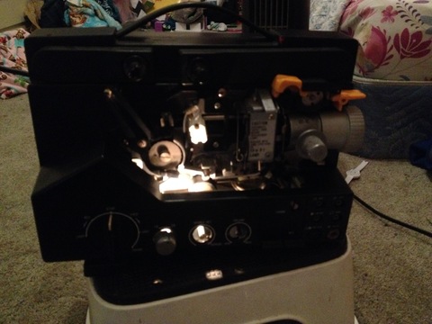
Look at it, ain't it pretty all lit up?
For the Love of God Sankyo, what are you doing to me?
Posted by Steve Klare (Member # 12) on June 20, 2017, 01:47 PM:
Hi Peter,
A real bad transformer is unusual, but not impossible. There are a lot of things that are more likely than that. They are also expensive and hard to substitute, so that shouldn't be a first guess.
Most of the time there is just one fuse on these machines. If anything at all works, it's intact since it is there to power everything.
On some PC boards with fine traces you may find small board mounted fuses to not allow the large currents that the main fuse would ignore to fry them, but something as powerful as the transport motor or the amp would almost certainly be protected just by the main fuse.
With a DC motored machine, there would need to be some sort of speed regulator to keep you either at 18 or 24 FPS. Usually these are built up on a power board. This is seperate from the sound board on the machines I know.
Do you know if the board you repaired is a sound board or a power board? If there are wires to the switches that control the motor it's power. Wires to the speaker? -Sound.
I think it's likely that your motor controller is what failed in the first place, and it took out that bridge rectifier while it was at it. The rectifier could fail all by itself, but it could also be an innocent bystander!
Do you have some kind of multimeter there?
Posted by Peter Gilabert (Member # 5948) on June 20, 2017, 02:25 PM:
Steve,
Thanks for your feedback.
Judging by the other threads- especially for the Sankyo 600 motor one- that it's likely the speed controller, too.
What exactly that means I still need to figure out but I can tell you this:
Those two regulator devices that have screwdriver slots openings (18 & 24 I presume are on the big board with the capacitor and the rectifier that I replaced, along with some contacts that connect with the speaker contacts that are part of the back case.
So it appears all that stuff's on the same board.
Yes, I have a multimeter and I'm starting to even understand how to use it- I know you always want to set it higher than what you're testing at least.
So if you have an idea of what I should check I'll go for it!
Thanks !
Posted by Steve Klare (Member # 12) on June 20, 2017, 02:38 PM:
The two potentiometers are an excellent clue that this is a power board and the motor controller is there.
How I would approach it (at least to start) is to use the Ohms function to try to trace where the (+) and (-) terminals of the rectifier you replaced go. This may lead you to where the real problem is.
Does anybody have some sort of a schematic for this machine? This is a road map to everything that is connected up in there and operating without one is trying to find a specific house in a city of 100,000 people just by making guesses!
Posted by Peter Gilabert (Member # 5948) on June 21, 2017, 12:59 AM:
Yes, a schematic would come in handy! Anyone?
In the meantime, I've noticed that the path from where the yellow and white wires for the motor plug into the board lead to these black and yellow devices:
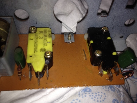
Could one or both of these be the motor controls I wonder?
AND, these both lead to something else that might be funky:
That WHITE STUFF all around this component (transistor?) with three wires seems pretty suspicious.
When I flip it over it looks like this:
I haven't tested these things with my multimeter yet, but I do feel like I'm looking for a needle in a haystack without a schematic.
Plus I'm reading you gotta de-solder some of these things first (to get readings), which I can do- but could take a loooong time.
Oh, boy.
Posted by Brian Fretwell (Member # 4302) on June 21, 2017, 03:12 AM:
I would hope that the white stuff is to assist heat transfer from the transistor to the heat sink it is bolted too. (there is a name for that sort of compound, but I can't think of it at present "Thermal xxx" ? )
Posted by Steve Klare (Member # 12) on June 21, 2017, 06:09 AM:
The white stuff is thermal compound. It is this thick white glop designed to fill in the gaps between the transistor and heatsink and improve heat transfer.
It is loaded with beryllium powder and if ingested is poisonous. Its industry nickname is "the white death". (Just don't EAT it! Wear gloves or at least wash your hands thoroughly afterwards.)
If you are going to take the transistor out anyway, you may as well replace it. Are there part numbers visible? (Hint: clip the leads before you start to desolder. Hint 2: at least have a replacement device in the mail before you do anything.)
The transistor is probably the device that controls the motor current (and speed). If there was a short around the motor, it's probably toast. It's 40 years old anyway.
Those two other things are the switches that control motor direction. Each is wired to (+) and (-) and the third terminal is to one side of the motor. Each selects the opposite what the other does to spin the motor one way or the other. When they select the same, (I'd make it "-") the motor has no voltage and stops. What they select is dictated by cams on the control knob shaft in the machines I've taken apart.
A short around or inside one of these switches could cause all sorts of havoc.
Posted by Peter Gilabert (Member # 5948) on June 21, 2017, 08:51 PM:
So I got my replacement bulb in the mail today and- voila! It works.
Now I suppose I'll try to figure out how to rest for shorts on the board with my ohms setting.
Once I figure out how exactly 😁
Thanks!
Posted by Peter Gilabert (Member # 5948) on June 22, 2017, 08:11 AM:
Also I can now see the code on the transistor, it reads:
T D235
Y '71
I've tried looking up what the modern equivalent to this is and I can't figure it out, it doesn't quite fit any code language I can find. Sure looks like a transistor, with it's three wires and all.
Anyone have a clue?
Posted by Steve Klare (Member # 12) on June 22, 2017, 09:36 AM:
Your transistor is most likely D235 and the "T" is probably "Toshiba". "71" is the date code (I was nine years old!)
I'm seeing NTE152 described as a modern substitute. They are out there and common, too. (Newark Electronics has them, probably others too.)
I'd clip the old one out and check it with an ohmmeter just for morbid curiosity. A good one looks like this:
(+) on base (-) on emitter: low resistance
(+) on base (-) on collector: low resistance
(-) on base (+) on emitter: high resistance
(-) on base (+) on collector: high resistance
You can probably get away with replacing the thermal goop with a sil pad. They are a lot easier to deal with and I see them used in a lot more demanding applications than this.
My gut is telling me this is probably not THE problem, though. I'd think it was more the transistor by itself if the complaint was "My projector runs very fast and doesn't respond to the frame rate switch". (Just saying!)
Posted by Peter Gilabert (Member # 5948) on June 22, 2017, 11:51 AM:
Toshiba that's what I thought too.
I called Mouser and they suggested this:
BJT BUP NPN 5A 50v Bipolar transistor
I ordered it, hopefully either theirs or yours would work (?)
Posted by Steve Klare (Member # 12) on June 22, 2017, 12:09 PM:
D235 is (was?) a 50V, 3A device. You have met and exceeded those specs.
I suppose if the Beta (current gain) of the replacement was too low you'd struggle to reach 24 FPS, but that's about as bad as it could get. (Don't know that one way or another anyway...)
You should go over those switches with the ohmmeter: open circuit between the two unswitched terminals, switching action from the third switched one to the other two: switch closure to only one at a time.
Posted by Peter Gilabert (Member # 5948) on June 22, 2017, 03:12 PM:
Steve,
Thanks for your help,
Kind of embarrassed but I don't understand exactly what you're saying to do with the switches, perhaps I need to learn more about using a multimeter
Peter
Posted by Steve Klare (Member # 12) on June 22, 2017, 03:31 PM:
Well,
An ohmmeter is kind of like an honors' class continuity tester. You can see a short circuit, an open circuit and all the shades of circuit in between.
If you put the meter in "Ohms" and touch the leads together, you will see zero or something really close. This is a short circuit.
If you take them apart you will see something like "OL". This is an open circuit.
If you touch both of them with your fingertips you will often see some large number, because walking bags of salt water which we are, we conduct electricity. (It's only a small battery: no shock!)
-moral there is when making a real measurement, keep your fingers OFF the leads!
If you attach the leads to two terminals of a switch and the switch is closed, you will see some number close to zero. If you open the switch, it will swing up past the maximum measurement possible and read "OL".
-This is what switches do: let you choose short circuit or open.
Posted by Peter Gilabert (Member # 5948) on June 24, 2017, 01:57 PM:
Well,
Right now I'm the Poster Child of Frustration.
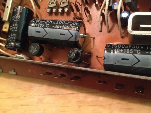
While waiting for my new transistor (which may won't fix anything anyway), I went ahead and replaced two other nearby capacitor and the other rectifier.
Plugged it all in and- BACK TO BURNING WHITE SMOKE.
Shoot me now.
The new one I just put in last week is fried:
The thing is, It didn't smoke and fry anything AFTER I replaced it before, so the only explanations I have are:
1) I noticed a tiny break in the circuit line next to (the one that just burnt) that I fixed this morning with solder just before I plugged it in, meaning it would've burned last time anyway.
2) I replaced the wrong kind of two additional capacitors this morning- because they are the same- except they are both rated at 50v instead of 25v. I thought that was safe but maybe?
And just for good measure, my de-soldering pump broke.
Kinda over it, ready to throw in the towel.
Posted by Maurice Leakey (Member # 916) on June 25, 2017, 03:25 AM:
Peter
You have tried very hard. But some old projectors just can't be saved.
Let us hope that you can find a replacement that's in good working order.
Posted by Steve Klare (Member # 12) on June 25, 2017, 07:04 AM:
These are tough because of the lack of information. With a schematic you know where to look and what to try when you are troubleshooting. This is just guesswork. It can and does work, the odds are just more against it coming out that way.
I found myself in a similar position with one of my favorite projectors once. I found a really excellent parts donor (chassis damaged but mechanical and electronic parts were mint) and just swapped out the entire assembly.
I had an adventure with a Forum Friend a couple of years ago where we troubleshot a similar failure by E-mail. It probably took a month on and off by the time he got parts, but it worked out. What made the difference? -the schematics he sent me. The whole discussion was based on them.
Sometimes it pays to buy a good condition machine of the same type, call the one you already had a parts machine and call it a day.
Posted by Janice Glesser (Member # 2758) on June 25, 2017, 09:57 AM:
@Steve... Great advice.
@Peter... Don't be too discouraged. I know it's frustrating, but think of all the electronics knowledge you have accumulated in the process. I once took an entire projector apart to figure out how to install a new motor belt. After all the parts were laying out on the work table... I still couldn't figure it out. So I devised a method to make my own urethane belt that didn't require any disassembly. So there are really no failures...just knowledge gained.
Posted by Peter Gilabert (Member # 5948) on June 25, 2017, 04:49 PM:
Yes,
Thanks for the feedback all!
Posted by Phil Murat (Member # 5148) on June 26, 2017, 11:39 AM:
Hi Peter,
I understand you replace components (Rectifier(s) Bridge(s) & Capacitors) but one of them failed again.
Is the last picture showing new components ?
If Yes, one bridge looks out of order.
Could you tell me parameters for these Bridges (means Voltage rate and Current )
If you have no reference for Bridges, you can get an idea like this :
Current 3A = 1 square mm for component terminal/wire section (Approx)
Is there any fuse between Transformer and rectifiers ?
Try to disconnect wires (for Amplifier or Motors) which are normally localised between Rectifying stage (Bridge + Capacitors).
"Power on" Projector and check output DC Voltage after from output Bridge.
If All is OK (means No fume and No Over heating observed) there is a high probability for a Short Circuit Just After Rectifying Stage.
Let us know.
Posted by Steve Klare (Member # 12) on June 26, 2017, 11:59 AM:
It's the difference between finding "A" problem and "THE" problem. (1)
There's a short in there someplace! The rectifier is just an innocent bystander which got caught in the crossfire.
NOTES:
(1) About 10 years ago my clutch wasn't releasing. A mechanic said my clutch was worn and charged me $750 to replace it. (That was A problem).
I got the car back and a few days later found out THE problem from the start was a worn out $150 clutch cable which I then replaced myself.
(If I'd known that all along...)
What's the difference between A problem and THE problem? -in this case 750 dollars!
Posted by Peter Gilabert (Member # 5948) on June 26, 2017, 03:29 PM:
I applaud the selfless generosity of the members' time and advice here. Perhaps I shall tackle the Sankyo but now that I have a working B & H, in a less fervent manner.
That way I'm not so pissed off all the time .
![[Big Grin]](biggrin.gif)
Posted by Steve Klare (Member # 12) on June 26, 2017, 04:15 PM:
Sometimes the best thing to do is put it away and do something else for a while.
If you go back to it, how I would deal with this is snip out the burnt rectifier, hang an ohmmeter on the (+) and (-) terminals, (hopefully) observe the short circuit and then start disconnecting and reconnecting things from the motor, through the switches and then back to the board watching to see when the short disappears.
-at least then you know what general neighborhood your troublemaker is hiding in.
Plus: troubleshooting with no power, and no smoke!
Visit www.film-tech.com for free equipment manual downloads. Copyright 2003-2019 Film-Tech Cinema Systems LLC

UBB.classicTM
6.3.1.2