This is topic GS1200 Blower Motor Connections in forum 8mm Forum at 8mm Forum.
To visit this topic, use this URL:
https://8mmforum.film-tech.com/cgi-bin/ubb/ultimatebb.cgi?ubb=get_topic;f=1;t=013119
Posted by Paul Adsett (Member # 25) on September 26, 2019, 07:25 PM:
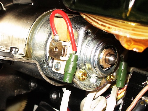
Well, talk about cascading system failures, I now find that I have broken off one of the main blower motor leads, which may or may not explain why the blower motor is not running! ![[Big Grin]](biggrin.gif)
Anyway the question for Leon and anybody else is "what are those two green things spliced into both leads going to the motor brushes? Are they just there for stress relief/support of the wires, or are they something more sinister? Can I just ignore them if I connect a new wire up directly from the relay to the motor? The existing motor wire is extremely fragile,no wonder it broke off.
Posted by Mark Norton (Member # 165) on September 27, 2019, 01:43 AM:
Hi Paul, they surpress motor noise that will otherwise be picked up by the amplifier. One snapped off "flush" on mine too, I found it very difficult to solder back on.
I would like to know if there are replacements available for these.
Posted by Phil Murat (Member # 5148) on September 27, 2019, 02:20 AM:
Hello Paul,
Green Cylinders :
It looks to be "Coils" ("Selfs" ?) installed in a serial path to increase motor performances or decrease arcing at brushes areas.
To be confirm.
Could you record "R" for these coils ? (Normaly "R" value is very low, may be below 10 OHMS, depending on lenght of coil wire).
"Selfs" can be found on Electronical Components Market. However, due to numerous configurations (Torus, Cylinder, With or Without core, Wire section, etc....), you need to find out some datas to determine Self Class.
Otherwise, may be (in order to save existing coil) it is possible you roll out a portion of copper wire from the fail green coil and simply renew soldering to link it to motor terminal....
[ September 27, 2019, 03:33 AM: Message edited by: Phil Murat ]
Posted by Paul Adsett (Member # 25) on September 27, 2019, 08:34 AM:
So these two green things are classified as inductors ?
Measured resistance across these at 0.3 ohms
As Mark has observed it is just about impossible to resolder these if the wire has broken off at the end of it. Is it safe for me to by-pass this for now to see if I can get the blower motor running?
Posted by Phil Murat (Member # 5148) on September 27, 2019, 10:43 AM:
You are right Paul, "inductor" is the right name :
[URL=INDUCTOR for sale]https://fr.aliexpress.com/item/32812559693.html?spm=a2g0o.productlist.0.0.2aa31f65bOzAyL&algo_pvid=41ee612c-c24f-4a1b-aab6-8e40e7c0cdc5&algo_expid=41ee612c-c24f-4a1b-aab6-8e40 e7c0cdc5-14&btsid=064984b8-f905-40c8-b373-e344bf316b4d&ws_ab_test=searchweb0_0,searchweb201602_1,searchweb201603_52[/URL]
Bypassing failed inductor will increase arcing condition, so that arcing could be observed on relay contact diminishing relay life.
Also , unwanted extra noises can be reported on sound.
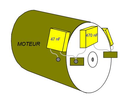
May be 3 capacitors could replace both inductors (unpolarized capacitor fitted on motor terminals,1 in // installation + 2 links beetween shell and terminals ), but I have no idea of capacitor value, and it is better to get wiring diagram before to make any change.
Here is an exemple for a small filtering system which works pretty good for small motors (scale models , etc...).
To be efficient, it is recommended to get capacitors terminals shorter as possible...
Posted by Leon Norris (Member # 3151) on September 27, 2019, 11:41 AM:
Paul, The red wire is the bottom! It runs to the lamp relay circuit board and the top wire runs to the lamp relay! I have the fan motors in stock still sealed! They have the wires on them! Good luck!
Posted by Maurice Leakey (Member # 916) on September 27, 2019, 02:45 PM:
For details click below re inductors:-
https://www.aliexpress.com/item/32812559693.html
Posted by Phil Murat (Member # 5148) on September 27, 2019, 03:19 PM:
Thanks Maurice, so these ones are 20mm x 3mm, wire 0,7mm ?
Value is 6,8UH
This is what I understand, it looks to be closed to the green ones.
Wire is probably a bit stronger than greens.
Posted by Paul Adsett (Member # 25) on September 27, 2019, 05:28 PM:
Thanks Phil, Mark, Leon, and Maurice for all the helpful advice. Right now my GS1200 has ended up on life support in the ICU following what was thought to be a minor problem with the take up not rotating. Amazing how these GS1200 jobs can rapidly escalate in terms of complexity and cost.
Anyway my next question is how critical are the specs for those inductors. Will any RF Choke with say a few microhenries of inductance (a few turns on a ferrite core) do the job, or does it have to be 'tuned' as in an LCR resonant circuit, in other words does it has to be a specific value of inductance to suppress arcing at the brushes and relay contacts?
UPDATE
I was able to solder the lead from the relay back onto the green inductor, albeit a very weak solder joint it at least makes the connection good enough to test the equipment. Anyway one of the main fuses blows immediately on turning on the main power switch and everything is shut down except for a couple of lights. None of the motors are running.
[ September 27, 2019, 07:50 PM: Message edited by: Paul Adsett ]
Posted by Phil Murat (Member # 5148) on September 28, 2019, 06:15 AM:
Hi Paul,
I am not specialist in Electronic systems but I don't think that filters generaly used to cut noises due to motor arcing are built as resonant circuit RLC more often used in radio system and tuned up for a specific frequency.
I assume in our case the idea is only to damp or absorb what happens in brushes area.
Concerning fuse burnt, I suggest you to investigate around power supply (after bridge rectifier).
If a transistor (power regulator) has failed, it is necessary to find out origine of defect (miscelaneous short circuit and/or failed big capacitor, etc.....) before to replace it.
Did you test the Fan motor with a seperate power supply ? (Motor has to be fully unplugged to do that)
Do you have schematic or wiring diagram for your machine ?
An other idea :
Reviewing your picture, it appears broken wire is linked to a Red one on motor (Normally Positive current).
So if this broken wire has incidentally hit shell of motor, this could result in a big short cut which could heavily damaged the power governor circuit just before....
[ September 28, 2019, 09:19 AM: Message edited by: Phil Murat ]
Posted by Paul Adsett (Member # 25) on September 28, 2019, 11:41 AM:
Thank you Phil. I am going to replace the large relay ( the original problem) and a couple of rectifiers in the faint hope that this may do something. I am not at all optimistic and I think the main control board is probably seriously damaged, although visually it looks fine. Finding someone to fix something like this is very difficult and I don't think anyone here in Orlando will look at it. I would think you need a 'breadboard' machine to be able to trouble shoot the problem. Maybe Leon can fix it, or he has a replacement control board.
Posted by Phil Murat (Member # 5148) on September 29, 2019, 01:54 PM:
Hi Paul,
Yes , my feeling is the issue is around one of the power supply stages too.
Could you tell me if bottoms of Big "blue" caps are perfectly flat (idem for black ones next to these ones) ?
Anyway , I suggest you to replace them in a same time you renew bridge rectifiers.
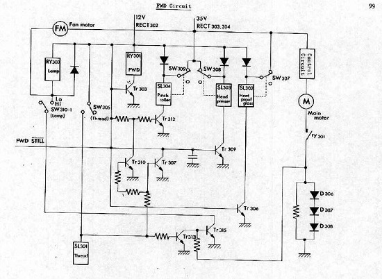
But, at this time, I have a problem to find out a "Datasheet" for voltage regulators (4) D330 just below flywheel,Some of them appears in P99.
- what is the fuse which breaks ?
- Does it breaks when you power on the machine or only when you play forward?
To follow
NB
Have you got this schematic ?
[ September 30, 2019, 04:09 AM: Message edited by: Phil Murat ]
Posted by Paul Adsett (Member # 25) on September 29, 2019, 04:02 PM:
Hi Phil, thanks so much for taking your time to try and helpme out - much appreciated.
Ok so the blue caps all look visually like new, all flat bottoms as far as I can see without removing them.
The fuse that is blowing is one of the 3 amp fuses on the board attached to the main transformer. There are two 3.0 amp fuses which are oriented vertically and it is the one on the left looking into the back of the projector.
This fuse blows instantly when the main power switch is turned on.
The lamp is still going into its preheat mode and the amplifiers
signal level meters still light up, but that's about it. None of the motors are getting power.
What is the operating voltage of the fan motor?
[ September 29, 2019, 07:36 PM: Message edited by: Paul Adsett ]
Posted by Phil Murat (Member # 5148) on September 30, 2019, 03:54 AM:
Hi Paul,
Your first idea to replace RY303 seems to be a very good way.
If you have no spare available at this time, try to remove it and save (this is just to make troubleshooting) by soaking it using a powerfull contact cleaner (choose cleaner-lubricating too). you can manage a small hole in crystal shell to insert the spray pipe. the idea is to get inner contacts free and clear from all oxyde you can. Then test relay outside with a small battery (max 12V) observing contacts motion and their good position (contacts have to swith all together).
Moreover, test (and insure you) Fan Motor works properly with a 12V battery (disconnect motor from machine of course)
Fan Motor works under 35V at full power and just around under 12V when idling (Lamp Off / Preheating) and actuating flywheel.
4 RECTIFIER stages:
A) +35V powers Fan, Main Motor (via governor), Amplifier (Vertical Fuse 3A) :
To renew 35V power stage you need 1 Rectifier 1B2C1 (RECT 303) + 1 Rectifier 1B2Z1 (RECT 304) + 1 Capacitor 2200µF/50V (C317)
B) +35V Amplifier (Vertical Fuse 3A) :
1 Rectifier 1B2C1 (RECT 305) + Rectifier 1B2Z1 (RECT 306) + 1 Capacitor 4700µF/50V (C318)
C) +12V Amplifier , Miscellaneous (Relays, etc...)(Fuse 5A) :
1 Bridge S4VB20 (RECT 302) + 1 Capacitor 4700µF/16V (C316)
D) +5V T/U & Rwd Motors (Fuse 5A) :
1 Bridge SIRB20 (RECT 301)
(In case some references are no more supplied , you can install an equivalent)
1B2C1 - 1B2Z1 DATASHEET
NPN transistors which are following works in the Logic Schema p99 (transistors don't like short circuit) :
TR303 / TR307 / TR 310 / TR313 = 2SC945
TR306 / TR309 / TR312 / TR315 = 2SD330 (Installed below Flywheel, taged D330)
D330 :
2SD330
2SC945 :
2SC945
As necessary Both references are still available for few money (Ebay or anyplace else).
Let us know ...
[ September 30, 2019, 08:49 AM: Message edited by: Phil Murat ]
Posted by Paul Adsett (Member # 25) on September 30, 2019, 09:11 AM:
Wow, that's extremely helpful information, thanks so much again Phil. ![[Smile]](smile.gif)
Posted by Phil Murat (Member # 5148) on September 30, 2019, 10:08 AM:
Thanks Paul for your comments.
Thinking again about this failure and in the case you need to remove "Primary board", it could be "cost effective" to take the opportunity to make a "refresh package" (Rectifiers stage, Caps & relays replacement) depending on times accumulated by your machine... ![[Roll Eyes]](rolleyes.gif)
Posted by Paul Adsett (Member # 25) on September 30, 2019, 02:47 PM:
Good advice Phil. I already have the control board removed from the projector .
Posted by Paul Adsett (Member # 25) on October 02, 2019, 03:20 PM:
Before starting any replacement of components on the big control board I did the following:
1. I removed the small motor board which plugs into the control board.
2. I switched on the power and the fuse did not blow, and the main blower motor now powers up and the lamp lights up in preheat mode.
Does this mean that the motor board is the problem ? Can it be repaired?
Posted by Steve Klare (Member # 12) on October 02, 2019, 03:35 PM:
There is a GS service manual with schematics in the Manuals section.
I looked them over...looks challenging!
Given some patience, I bet you could piece a motor control schematic out of all the fragments.
Posted by Phil Murat (Member # 5148) on October 03, 2019, 01:42 AM:
Hi Paul,
Very High probability you found out "issue root" ![[Wink]](wink.gif) :
:
Upon some research in forums backgrounds from my side (German Forums too) some GS1200 owners have reported this typical problem (35V fuse burnt due to failed "Governor").
Often time , when "Governor" board fails, it generates a short-circuit on 35V power supply.
I/C UPC1002C fitted on "Governor" Board is probably out of order due to poor caps around.
Also it can be an aging failure which shows up for machines which have accumulated many working hours.
UPC1002C is an I/C "NEC" component, a bit difficult to get , but still available (minimum price around 5Eur in China) .
In case "Governor" refurbishment option is choosen :
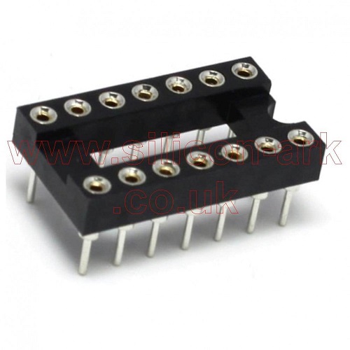
A) To remove UPC1002C, it can be more confortable to cut pins before and to desolder each pin by each one in order to limit stress of board.
B) Install 14 pins DIL socket on board first then simply clip new IC on socket.(This minor modification allows fast future installation/removal of I/C)
Pay particular attention during socket and I/C : Do not reverse their position
C) Suggest to replace all caps and small transistors as an corrective action package.
14 PINS DIL SOCKET Suggested :
[ October 03, 2019, 05:56 AM: Message edited by: Phil Murat ]
Posted by Thomas Knappstein (Member # 6134) on October 04, 2019, 06:19 AM:
Hi Paul!
It sounds like your Main Motor Power Transistor is shorted. It is the big one on the heat sink Plate. you only can see the three lines going on his Pins. (Red Blue Yellow). It is possible that the little Control Board is defective too. But first check the Main Motor with a seperate Power Supply. If this Main Motors getting older, they take more Amps from the electronic and overheat it.
Posted by Paul Adsett (Member # 25) on October 04, 2019, 09:49 AM:
Thomas, what do you mean by "the main motor"? Is the main motor the fan motor, or the one that actually drives the mechanism via the rubber belt?
Can you possibly post a picture or diagram which points out the location of that main motor power transistor.
Posted by Phil Murat (Member # 5148) on October 04, 2019, 10:55 AM:
Hi Paul,
"Main Motor" in this case is claw motor.
The power transistor which "finaly" controls "Main Motor" is 2SD110 (also called "Darlington" and needs to be properly cooled and vented).It can stand maxi 100W , here is its data sheet :
2SD110 POWER TR
It is referenced as TR451 at P98 from PDF file.
This transistor received its signal from "governor" board on pin 1 (Base).
Here is my analysis:
2SD110 is located out of "Governor". In case 2SD110 is Fully shorted (assuming short circuit is between pin 2 emiter and 3 collector-case) , you should get a permanent short-circuit causing fuse to blow out even if "governor" board is removed....
I understand fuse does not blow out when "Governor board" is removed.
It is a good idea to make a check up for "Main Motor" (Run main motor seperately and observ how it runs). In case this one is damaged, it will ask very high current (more than 3 A) which cause fuse to blow out (and 2SD110 to heat a lot)........ but only when you run machine fwd.
In your case, fuse is supposed to blow out immediately once machine is simply power up and main motor not running.
So this is what I understand, but may be I missed something...
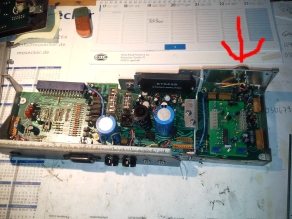
Posted by Thomas Knappstein (Member # 6134) on October 05, 2019, 06:03 AM:
Hi Paul!
On this Picture you can see the main Board of the GS 1200. I have marked the Power Transistor for the Main Motor wit a red Arrow.
I would do the following Way. solder the Transistor out and put the little Board back. Than swish the machine on. If the Fuse does not blow it will be the Transistor.
Posted by Paul Adsett (Member # 25) on October 05, 2019, 11:02 AM:
Thanks Thomas for that great tip! No I am not on facebook, but if there is a GS1200 repair group there then I will probably sign up!
Posted by Thomas Knappstein (Member # 6134) on October 06, 2019, 02:02 AM:
It is not a special GS 1200 repair Group Paul. It is for repairing 8 and 16mm machines at all. There are many People who know what they did. And it is easier to load up some pictures.
Posted by Paul Adsett (Member # 25) on October 14, 2019, 02:16 PM:
The big transistor checked out ok. I got the new large Matsushita relay installed on the board as well as new 1B2C1 and 1B2Z1 rectifiers. I also replaced the motor governor board. The projector is now fully functional in all modes, and the original problem with the take up not working is now gone.
I still have one thing to do and that is to find an inductor coil for the blower motor, since the original has broken off and there is no way to solder it back on as there is no wire sticking out from it. For now I have just cut it out and reconnected the wire directly from the relay board to the motor. Consequently I can hear some RF interference from the fan motor on the sound. I am trying to find a suitable substitute inductor. Any suggestions much appreciated.
Needless to say I am delighted to get this wonderful projector fully functional again, and I cannot thank Phil, Thomas, and Leon, enough for helping me through this complex repair process.
When I first switched the machine on after all the repair work, I had no idea what to expect, but my reaction was something like this:
https://www.youtube.com/watch?v=QuoKNZjr8_U
Posted by Thomas Knappstein (Member # 6134) on October 14, 2019, 10:31 PM:
Hi Paul!
Solder two 100nF Caps from the + and the- to the Motor Housing Ground. Than you can throw the green Coils both away and solder the Wires directly on the Brushes. I have done this on a machine, where the same Problem was. Works fine. No Noise in Speakers.
Posted by Paul Adsett (Member # 25) on October 14, 2019, 11:27 PM:
Thanks Thomas,but I am uncertain about the capacitance symbols you have used. Is that 100 micro farads?
Posted by Phil Murat (Member # 5148) on October 15, 2019, 01:07 AM:
Hi Paul,
Thanks for your comments and happy you get your machine back to work, "Congratulations" !!!.
It is normal you observe "noises" in sound as 35V used for fan motor is common with 35 V comming to Amplifier.
Concerning "green" inductors , this system is more efficient than a capacitors system because inductors work as a plug and is designed to cut a specific noise Frequency Band.
A capacitors system is supposed to work too but instead to work as a plug it works like (more or less) as a short cut and not for a specific frequency.
In case a capacitor fails , it will probably short cut circuit, damaging last transistor (Fan motor feeder).
However, "Inductors" are 100% fail safe !!
Frequency of the noise depends on Motor Speed X Number of inner copper collectors.
In reference to the schema posted above in this TIP , you need 3 unpolarized capacitors (propylen) to replace the dual inductances system :
- 1 Capacitor 470nf (Nano Farad)
- 2 Capacitors 47nf (Nano Farad)
Anyway, as it is highly recommended to keep this inductors system as noise suppressor, the good new is that an inductor can be done by yourself , like a copy of the original , knowing diameter of wire, diameter of core, total lengh , and keeping ferrite core.
[ October 15, 2019, 04:19 AM: Message edited by: Phil Murat ]
Posted by Paul Adsett (Member # 25) on October 15, 2019, 09:38 AM:
I'm wondering if there is anyway to determine the microhenry value of these inductors and how much fan motor current they should take. They don't seem to be identified in the GS1200 service manual, just part of the fan motor.
Any opinion on whether any of these inductors would work:
http://www.surplussales.com/Inductors/Chokes/Ind-MoldRFChoke.html
Posted by Phil Murat (Member # 5148) on October 15, 2019, 10:12 AM:
Hi Paul,
Not tested yet but I have just found that :
http://users.telenet.be/h-consult/Txradio/selfBerekening.htm
This is a little program in direct use.
Calculated value is (more or less) theoretic, because a same inductor will offer a fluctuating value depending on current fluctuation (this is the case because Fan motor has 2 different speeds)......
Generaly , at the end, the best way is to plug an oscilloscope and to determine if signal recorded is satisfactory.
Anyway when you don't ear anymore noise, game is won
Concerning current crossing inductors , take a safety margin :
If Fan Motor power is around 30W-40W, voltage is 35V , stable current is around 1 to 2 Amps
Frequency value to cut : using your ears you can determine an approximative value of the noise .You can Try 1000 HZ for exemple
An other one site but in French language (not tested) :
http://www.tavernier-c.com/bobinages.htm
It seems the usual name in English language for this inductor typical use is "Choke Coil" (To be confirm)
To give an other idea, an other product exemple, may be very closed, with detailed datasheet :
http://www.yfbalun.com/English/productshow_199.html
or
http://www.yfbalun.com/English/products_t29.html
[ October 16, 2019, 07:02 AM: Message edited by: Phil Murat ]
Posted by Thomas Knappstein (Member # 6134) on October 16, 2019, 08:42 AM:
Hi Phil!
The 35V for the Fan Motor are not the same a for the Amplifier. there is a seperate Coil on the Transformer and a seperate Rectifier with Cap for the Amplifier. With only two 100nF Capacitors it work as good as with the green Coils.
Posted by Phil Murat (Member # 5148) on October 16, 2019, 09:34 AM:
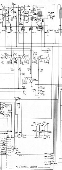
Hi Thomas,
In accordance with Elmo "wiring Diagram" (PDF P95/98) here below, I can see common 35V for "Fan Motor" and "Power Amp" :
However, may be I have missed something.
The filtering solution (3 caps) I have suggested to Paul is often used by people using models scale radio controled.
[ October 16, 2019, 10:41 AM: Message edited by: Phil Murat ]
Posted by Thomas Knappstein (Member # 6134) on October 16, 2019, 10:47 PM:
Hi Phil!
This is only a piece of the whole Diagramm you have posted.
On the right Side of your Picture are the three caps with their rectifiers. And there you can see that the Amplifier has a seperate rectifier with Cap 4700µF/50V and two Toshiba Rectifiers.
Posted by Phil Murat (Member # 5148) on October 17, 2019, 02:21 AM:
Hi Thomas,
You're right,and this is exactly what I wrote (page 1 of this Topic, 14th post).
In summary, Amp section (Power Amp + Pre Amp, to be confirm) is powered by 2 seperates 35V bus and a 12v bus too.
Posted by Thomas Knappstein (Member # 6134) on October 18, 2019, 09:06 AM:
Hi Phil!
Yes you are right Excuse me.
Posted by Phil Murat (Member # 5148) on October 19, 2019, 12:03 AM:
Hi Thomas,
No Problem, anyway GS1200 shows sophisticated and complex systems.
Posted by Paul Adsett (Member # 25) on October 19, 2019, 10:45 AM:
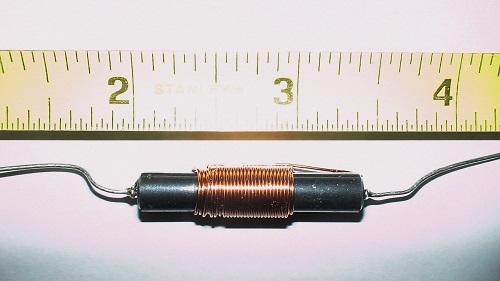
Well I went down to Radio Shack and picked up this 100 microhenry RF choke. I covered it with a tube of heat shrink and spliced it into the (broken) fan motor lead wire. I then switched on the projector, turned the lamp on so the fan was running at full speed, plugged in the earphones, and low and behold Zero EMI from the fan motor. This choked totally killed the noise. Stereo sound is now faultless. No doubt this particular choke is overkill, but it does the job, and there is plenty of room to solder it in by the motor.
Ain't science wonderful!
Posted by Phil Murat (Member # 5148) on October 19, 2019, 11:28 PM:
Hi Paul,
Great, you killed "noise" by a single shot, congratulations !!!
Coil wire section looks to be around 0,7 or 0,8mm, is it correct ?
N.B
Assume Doug will move this Topic in GS1200 room.
Posted by Paul Adsett (Member # 25) on October 20, 2019, 10:51 PM:
Phil, I have opened up a Technical topic named GS1200 FAN MOTOR INDUCTORS and link to this section so Doug can add it to the Technical Index.
Visit www.film-tech.com for free equipment manual downloads. Copyright 2003-2019 Film-Tech Cinema Systems LLC

UBB.classicTM
6.3.1.2