This is topic Beaulieu Take-Up Problem. in forum 8mm Forum at 8mm Forum.
To visit this topic, use this URL:
https://8mmforum.film-tech.com/cgi-bin/ubb/ultimatebb.cgi?ubb=get_topic;f=1;t=009823
Posted by Rob Young. (Member # 131) on March 10, 2015, 03:01 AM:
Well my Beaulieu is throwing it's latest tantrum. ![[Roll Eyes]](rolleyes.gif)
A couple of months ago, when switching to forward, the take-up spool refused to move. Switching to reverse then forward a couple of times and hey-presto, all was well again. I assumed it was the old washer in the arm wearing out, but when I dissembled it later, all was fine.
Anyway, I did a quick check in the back of the machine also and all looked fine, so I put it back together and it ran happily for the last couple of months.
Then on Saturday, during a show for friends (why do they always do this during a real show ![[Confused]](confused.gif)
![[Big Grin]](biggrin.gif) ) the same problem.
) the same problem.
A couple of reels ran fine, but then no response from the take-up arm. Switching from reverse to forward several times and finally (with a little clunk) the take-up mechanism started to work again and is now fine.
It must be a problem with the clutch not re-engaging following rewinding I guess? I've had a quick look at the service manual and couldn't see anything obvious.
Any one else had this problem? Someone tell me there is a really easy fix!! ![[Smile]](smile.gif)
One for our resident Beaulieu expert, Andrew, me thinks.
Posted by Maurice Leakey (Member # 916) on March 10, 2015, 03:37 AM:
Does it have micro-switches?
They can be a problem with some projectors when switching modes.
Posted by Rob Young. (Member # 131) on March 10, 2015, 01:37 PM:
I don't believe so in the case of forward / rewind, Maurice; I think it's mechanical although I may be quite wrong there.
Will try to delve deeper into the service manual when I get the chance.
The fact that once re-engaged I will run happily means at least that hopefully no cogs are damaged.
Any and all suggestions appreciated!
Posted by Andrew Woodcock (Member # 3260) on March 10, 2015, 02:02 PM:
Hello again Rob. Sorry it's taken a while to see this post and not respond to you sooner, but I have been in work since 5:30 this morning.
I won't be able to do much to help tonight pal as I don't want to start messing around getting my tools tonight after the day I've had but I will remove the rear cover on mine tomorrow when I am off and see what could be going wrong for you.
What I will say just off memory, you really don't need worry too much about this issue as the drive chain is very straight forward on the Beaulieu's. Anything after the motor drive belt has to mechanical with the exception of the threading system which does incorporate a micro switch and the capstan drive mechanism which can be tricky to diagnose when there are faults present.
If you can simulate the problem again between now and tomorrow afternoon it would be a distinct advantage to me as if you could take a video of the rear of the machine running with the rear cover removed, I would be able to see instantly which parts are turning and which are not. Then I could look at my own machine and track the possible faulty component that is letting the rest of the drive chain down on your machine.
If you feel you may be able to send me a short video while simulating the fault, please pm me Rob and I will send you my e mail so you can post it to me.
So in other words, it really won't be much at all that is stopping this from being the fully functioning exceptional machine that I know you are proud to own.
Chin up Rob, it really will be something or nothing I strongly suspect.
Posted by Rob Young. (Member # 131) on March 10, 2015, 02:36 PM:
Thanks mate; I'm out filming for the next few days but I'll run some films at the weekend time permitting and see what happens.
Please don't open up your own beloved machine just yet on my account. I'll see if I can emulate the problem first and report back.
When it fails again, I'll get the back off and see what's going on.
Meanwhile I'll study the service manual in my spare time.
Thanks, as usual for all your help Andrew.
https://www.youtube.com/watch?v=DlP7l8vkNOk
![[Wink]](wink.gif)
Posted by Andrew Woodcock (Member # 3260) on March 10, 2015, 02:57 PM:
Any help I can offer you Rob, you know you only have to ask. Taking the rear cover off mine is nothing unusual Rob when necessary for my own needs or to assist others with voltage readings etc, so you needn't worry about that mate.
I will do likewise with the manual tomorrow Rob and let you know what my gut instincts tell me. Bear in mind many machines have an intermediate gear that swings to the left or right on a small lever from the first driven gear off the belt. This floats from driving the rewind gears to the take up gears in many cases.
These do have a tendency to stick "on" one way or another instead of "swinging" inbetween the two gears as they should if the pivot point has dried out somewhat.
I have experienced this many times on an ST1200 as well as my Eumig S938 but never on my Beaulieu so far so I would have to check tomorrow if it even incorporates this same design feature, but a very common fault resulting in the same end result you have if indeed it does.
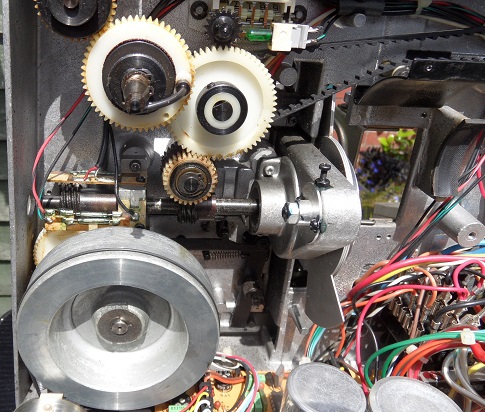
Having looked at the photo below to remind myself of the set up in there, I am certain the above only applies to AC motor driven
set ups. When the motor is electronically controlled the drive chain is simply reversed electrically through polarity switching to the motor I am sure, so the above cannot apply to these type of machines I think.The clutches on each of the drives do the rest I think. Its late now so I will check this for certain tomorrow now Rob.
"We will indeed fix it like new!"
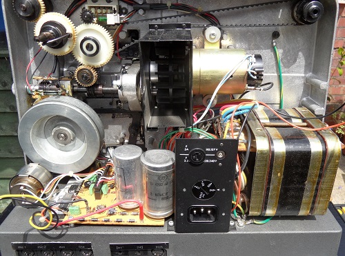
Not a great deal to the drive chain as said Rob. Please see photograph below with the main motor removed to simplify the drive chain and expose possible problematic parts further:
[ March 10, 2015, 05:07 PM: Message edited by: Andrew Woodcock ]
Posted by Andrew Woodcock (Member # 3260) on March 11, 2015, 10:36 AM:
Just checked the Bauer and the Beaulieu this morning Rob for the forward and reverse movement.
They work in the manner I suspected where the motor itself reverses and therefore directly reverses the drive on both of these electronically controlled DC driven machines.
AC motor driven machines like the ST1200 or S938, simply do not have this option as there is no way to electrically reverse the motor (single phase) so they have to attempt to do this mechanically in the manner I described above using an intermediate spur gear arrangement toggling from one gear to another either side of it.
This means that from the above photograph, every part of the drive should rotate continually while ever the motor is turning from the worm gears on the main shaft upwards. Only the one way clutches and mechanical linkages etc will decide in what mode one spindle turns or doesn't be it in forward, reverse projection mode or indeed rapid rewind mode.
This hopefully will narrow your search down somewhat Rob especially if you can simulate the fault with the rear cover removed.
Keep is all informed buddy.
[ March 12, 2015, 06:15 AM: Message edited by: Andrew Woodcock ]
Posted by Andrew Woodcock (Member # 3260) on March 12, 2015, 05:57 AM:
Had another look into this for you this morning Rob.
The only linkages that come from the main switch cam shaft, control the sound head section mechanical movement and the floating roller movement around the capstan drive roller area. That is it.
No linkages are utilised for spindle movements.
With the rear cover removed on my machine, I placed the machine into forward and reverse projection modes on the master switch.
All that changes is the rotation of all gears and the take up reel drive belt. Everything turns in both modes while ever the motor is turning.
So how then does the machine know only to turn the take up spindle in forward mode while leaving front arm spindle stationary and vice versa in reverse I hear you ask?
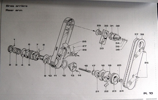
Simply that each arm has a ratchet mechanism built into the gearing at the lower end of each arm.. see drawings below.
This one way clutch or ratchet mechanism simply allows the spindles to be only engaged with the drive only ever in the direction that each of the spindles will ever turn or be driven.
In the opposite direction, the lower gear is still turning away as normal but the ratchet mechanism or one way clutch, simply rides over the ratcheting drive points.
Conclusion:
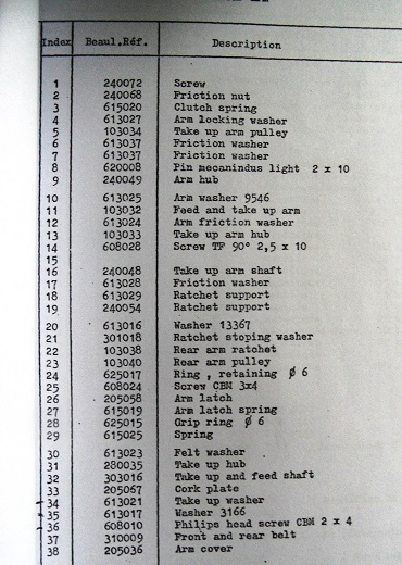
If, with the rear cover removed, you observe all gears and take up belt turning in both directions as you switch the master switch from forward to reverse, then the only other reason why the spindle cannot turn is either because the ratchet drive key (item 22 on page 10 of the service manual) is not engaging correctly with the ratchet drive wheel or there is wear to the ratchet drive wheel or the internal arm belt (item 37 on page 10) is either worn, loose or snapped.
Please refer to drawings below in your manual :
[ March 13, 2015, 12:40 AM: Message edited by: Andrew Woodcock ]
Posted by Rob Young. (Member # 131) on March 16, 2015, 05:37 AM:
Andrew, just wanted to say thanks for all your input and help so far.
Unfortunately, I've only had a chance to briefly try the Beaulieu yesterday. Of course, all now seems fine and it simply won't reproduce the fault.
When I get a little more time, I'll take the back off and have a proper look.
Thanks again for your posts and I'll keep you updated!
Posted by Andrew Woodcock (Member # 3260) on March 16, 2015, 12:27 PM:
Hope when you do Rob, it becomes apparent very quickly for you based on all of above mentioned.
Keep us updated then Rob please as you say, I will be really interested in the outcome as I am sure will others with these machines.
[ March 17, 2015, 04:27 AM: Message edited by: Andrew Woodcock ]
Posted by Rob Young. (Member # 131) on March 21, 2015, 07:45 AM:
Right, so I ran my 600 footer of "Genevieve" last night and half way through the take-up failed...quite amusing actually as it was the scene where Genevieve is towed into the garage. How ironic. ![[Frown]](frown.gif)
So...with the back cover removed, all works fine in reverse / forward. So Andrew, my friend, you are correct; it must be the ratchet failing.
It's so annoying because it only fails now and again, so it is now running fine again, but it did fail with the back cover off just now.
Right then; how do I fix the ratchet??
Posted by Andrew Woodcock (Member # 3260) on March 21, 2015, 09:50 AM:
Just take the full assembly apart Rob. Compare all parts to the drawing and see what is worn or whether or not the ratchet drive key (22) is Sat correctly in the assembly.
Just a thought, but did you take the reel arm cover off it just to see that the reel arm drive belt is tensioned correctly and not worn etc etc?
Highly unlikely to be this, but worth checking Rob just before pulling the ratchet assembly apart.
Have you renewed your friction linings in the past in this area Rob? This just may have dislodged the ratchet drive key perhaps if indeed you have?
Posted by Rob Young. (Member # 131) on March 21, 2015, 10:47 AM:
Yep, the belt is fine, Andrew, so the next step is carefully taking the ratchet assembly apart...wish me luck!
Posted by Andrew Woodcock (Member # 3260) on March 21, 2015, 11:06 AM:
You'll be fine Rob, I am certain. All here to assist if necessary as ever Rob! Best of luck to you mate.
Posted by Rob Young. (Member # 131) on March 21, 2015, 11:50 AM:
Andrew, what do you think is the best way to remove the retainer clip (part no. 24)?
Posted by Andrew Woodcock (Member # 3260) on March 21, 2015, 02:05 PM:
With a decent flat bladed slim ish screwdriver and a terminal flat bladed screwdriver Rob as it is a snap ring not a circlip.
Use one with a large tip to push on the two ends of the clip while slipping a terminal screw driver underneath in the gap created between shaft and snap ring. Then simply pry the snap ring off and try your best not to lose or bend it whilst doing so.
If you do lose, bend or stretch any of these, don't worry I can post you some. I have loads in all the common metric sizes Rob.
Oh and don't forget to wear full PPE and carry out a full risk assessment prior to beginning any work or no doubt that'll be another excuse for ridiculous jibes coming back to me!! Lol
[ March 21, 2015, 08:11 PM: Message edited by: Andrew Woodcock ]
Posted by Robert Tucker (Member # 386) on March 21, 2015, 04:44 PM:
Rob, make sure you use the correct tools and not a screwdriver to do this or you could make things worse, Get yourself some snap ring pliers.
Hope that helps
Posted by Andrew Woodcock (Member # 3260) on March 21, 2015, 05:12 PM:
Oh here we go again!
I've done the job of removing and refitting snap rings tens of thousands of times in my lifetime with no problems whatsoever using the above method.
I have seen and read loads of manuals and videos of photographic equipment being repaired and many engineers prefer to use this quick and easy method rather than bother to have a 200 drawer Snap On tool chest with every single sized set of circlip pliers, snap ring pliers, spring compressors, bearing pullers etc etc etc.
The chances of Rob having the "said" 200 drawer tool chest at the side of his sideboard in his living room is pretty remote I would have thought, therefore with this in mind, this was a fairly simple solution to Robs dilemma I would have thought but seeing as you are the ultimate expert on all things projectors Robert,maybe I should pass over advising and trying to help anyone on here in their hour of need and leave it all down to you to post the service manual docs and then detailed explanation of what to do.
Then I can simply sit back and "chip in" to my hearts content with any little dig I ever can.
And you tell me to grow up!!
[ March 22, 2015, 05:10 AM: Message edited by: Andrew Woodcock ]
Posted by Robert Tucker (Member # 386) on March 21, 2015, 06:00 PM:
Funny how people who are members on this forum cannot give helpful advice to other like minded forum members.
There's obviously something seriously wrong here !?!
Unfortunately i don't really have the time for this childish and bullying behavior period !
Posted by Andrew Woodcock (Member # 3260) on March 21, 2015, 06:03 PM:
Strange?????
Posted by Rob Young. (Member # 131) on March 23, 2015, 11:16 AM:
News!
I've taken it apart and the ratchet claw is ok, but it sits on part 19 with a pin which extrudes back into part 18.
The hole which you can see on part 18 determines whether the ratchet engages or not, given the direction of turn.
Whist the pin on the ratchet part 22 is engaging, it does seems to have worn so that it doesn't engage firmly.
So the pin on the ratchet must be worn leading to occasional slippage and thus lack of claw engagement.
Of course, it could be wear to the hole on part 18 also. Or both.
Where to find a replacement ratchet and part 18???
It did all need some minor de-greasing, which may help matters, but I feel replacing the parts is the only sure way to go.
EDIT update!! Took the front arm apart. It is definitely the ratchet pin which is worn. The front arm ratchet pin is in much better shape. Unfortunately it is a reverse version of the take-up so can't be interchanged.
Disc part 18 is slightly more worn on the take-up arm, but pretty similar to the feed arm.
So I need a new ratchet. Don't see one listed at Wittners...
Posted by Paul Browning (Member # 2715) on March 23, 2015, 01:02 PM:
Hi Rob, does the part just need to be sharpened up, that is its profile, and the burrs removed, or has it just worn away, with out any means of adjustment. Is there any chance of a close up picture of both bits. I have one of these machines too and if the part is not available, i'll make the parts, lets see what we can do mate.
Posted by Rob Young. (Member # 131) on March 23, 2015, 02:10 PM:
Hi Paul, I'll take some photos tomorrow if I get the chance to make it clearer, but basically, the actual ratchet is fine. The problem is that on the back of the ratchet part, there is a small "prong" or pin, which fits into the hole on part 18.
When part 18 rotates in reverse, it pushes the pin to move the ratchet out of the way, and then when running in forward, it pushes it to engage and drive the take-up.
The pin on the back of the ratchet shouldn't really, I suppose move away form the hole on part 18, but it clearly has, as there are wear marks on part 18 (the disc) and this has basically filed down the pin.
Hope all this makes any sense!
The slippage may be down to grease, or lack of pressure form the spring (part 17) but once re-engaged, the hole in the disc (part 18) should drive the pin, and thus keep the ratchet in a fully engaged and locked position.
But now that the pin has worn down (by fractions of mm!) it has become temperamental.
The ratchet part is finished in black and you can compare the wear by looking at the front arm ratchet which is fine, compared to the rear arm ratchet which has a worn silver tip to the pin and is (under a magnifying glass!) shorter.
I fear the only resolve is to re-engineer the whole ratchet (part 22), or somehow replace the pin (which may be engineering micro-surgery!!)
Posted by Andrew Woodcock (Member # 3260) on March 23, 2015, 02:42 PM:
Rob, Wittners probably will have the exact parts if you send them the manual serial numbers. The parts they advertise are the stock parts they have for sale for the masses, but I believe there is hardly any parts from these machines that they do not have.
If that method draws a blank, then measure the pin accurately for length and diameter with a vernier calliper and a metric micrometer and then I can easily knock a couple of these up if they are just a straight plain pin.
Let me know how you wish to proceed Rob please and as Paul says, if you can post us all a photo of the pin outside of the assembly it will help.
Posted by Paul Browning (Member # 2715) on March 23, 2015, 02:48 PM:
Hello Rob, so can we get the pin out ?, when you say micro surgery, are you talking about a pin with a diameter of say, a few mm's, or the is this a dimple pressed through the material from behind ?. Making a pin will not prove a problem rob, I have access to material harder than any metal your likely to encounter, that includes, hardened tool steels, tungsten carbide stainless steel, but this will need to be fixed somehow, maybe an araldite will do, or industrial super glue. The down side is that it will ware out the part it comes into contact with !!!!, so these are sometimes designed to ware out the replaceable part, ie the pin, but perhaps your right, and it may need a redesign. Lets have a look at the pictures rob, I'm we can cure this, we are the "A" TEAM OF FORUMS after all.
Posted by Andrew Woodcock (Member # 3260) on March 23, 2015, 02:53 PM:
Paul, I wouldn't be wanting it made out any harder steel than the original as the pin should be the part to wear first not the Ratchet Support Plates with the holes in them.
If we start placing different harder materials in here then the hole it engages with, will just become worn and elongated in no time mate.
Posted by Paul Browning (Member # 2715) on March 23, 2015, 03:32 PM:
Yes Andrew that is my point, look at the picture's when rob gets them, the pin is the replaceable bit, how much ware has it caused the mating part. I would think if this is a part wittner keep, they are well aware of this, and will probably sell the mechanism as a complete item, or else they would be stuck with not being able to sell the other parts. I have not had this apart so its merely a stab in the dark, the exploded view is ok for knowing what goes where, but you have to get the part, physically in your hands, you find a possible better way. If the parts prove to be cheap enough, then there is no point reinventing the wheel.
Posted by Rob Young. (Member # 131) on March 23, 2015, 03:46 PM:
Guys, this is just brilliant support from you all, thank you.
I will try to get some detailed images up tomorrow.
Andrew, what do you reckon is the best way to contact Wittners; email or phone? It's a while since I was in touch with them, but I will see if they can provide the parts.
Paul, I think it is worth looking into what has gone wrong here with regard to perhaps making better replacement parts.
We are taking mm's. The small ratchet part seems to be made up from 3 parts, the ratchet plate plus two "prongs" which are fixed onto it. I'm not an engineer, but I reckon if I can get you guys detailed enough photos you will know how it has been made and maybe know how to make a better version!
I'm concerned as to why it has been able to come out of position and wear itself down...although maybe Beaulieu engineers didn't count on 35+ years of use!!
Pics tomorrow, and thanks again guys, you are the best!
Posted by Andrew Woodcock (Member # 3260) on March 23, 2015, 03:48 PM:
No you're right Paul,I haven't needed to start looking at any of these one way clutches on these either on mine yet.Most of the mechanical parts on these have a very robust reputation. They are not known for any particular mechanical weaknesses,so this fault on Robs I suspect is quite a rare one.
I know the friction washers need replacing after years of use but this is only to be expected given that these are a "designed in" consumable wear item. The wear to these is seriously accelerated if you use your machine to clean your films with as this does put a lot of strain on both the motor and the rest of the drive chain but they should last many many years if you use the machine only as intended.
As Rob says, maybe the slippage is due to the two Ratchet Plates not being sandwiched together under the normal spring pressure as they normally would and therefore perhaps a gap for the pin to disengage has been created.
If the spring pressure has not been exerting the correct pressure on the Ratchet Plates then I suppose it would result in what Rob is currently witnessing.
We will just have to wait and see, all will become apparent I'm sure once Rob gets around to posting the photos of the parts and the wear on them.
One thing I can say for certain, is that if Wittners can and will sell these parts you can bet your bottom dollar that they won't be cheap, but at least they will be brand new originals.
Rob, I have only ever contacted Wittners by e mail and then you could submit your photographs alongside the part numbers.
They would then advise which parts (if any) they could provide you with to carry out the successful repair.
As you say Rob, no need to press the panic button just yet and start re inventing the wheel at this stage! Lol
Incidentally, the best and by far most robust method of achieving a one way drive in engineering mechanisms, I have found are these
http://stieberclutch.com/
They come in all different sizes and they tend to outlive the bearings that are fitted on the same drive shaft.
Dependant on which way around they are fitted to the shaft, governs which rotation the unit locks or freewheels, so one unit does for either rotational requirement.
These are very very durable mechanisms indeed which also run silently in both directions unlike a traditional ratchet mechanism.
Posted by Paul Browning (Member # 2715) on March 23, 2015, 04:53 PM:
I have a dream, and a solution, need to see the pictures though.
Posted by Andrew Woodcock (Member # 3260) on March 23, 2015, 05:02 PM:
All good things.... Paul ha ha
Posted by Rob Young. (Member # 131) on March 24, 2015, 05:36 AM:
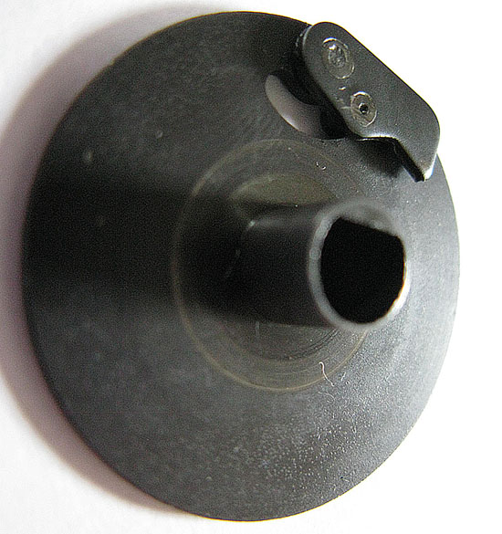
Here are some images to give you guys an idea.
First, parts 19 and 22; the ratchet in place on the first ratchet support disc.
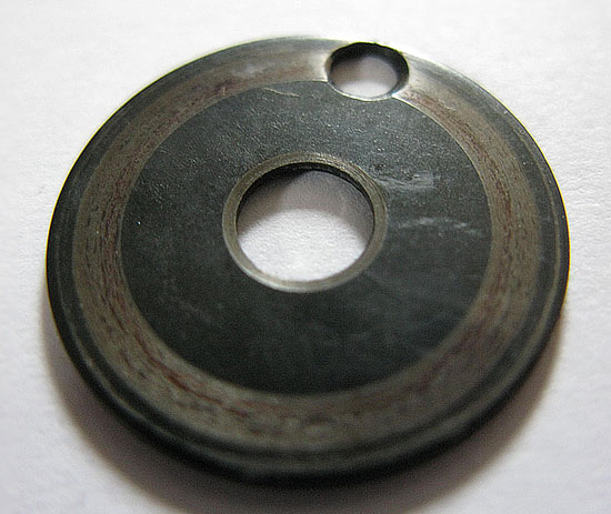
Part 18; the ratchet support disc which determines position of ratchet. Note the band of wear. This isn't present on the front arm part. I don't think it is significant enough to cause a problem, but shows that slippage has occurred.
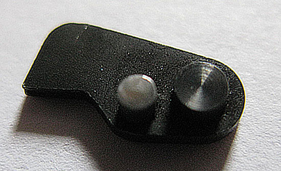
Part 22; the rachet removed form support and viewed from back. The slightly silver "prong" is the one which has worn down.
This is how it sits into part 19, viewed from the "back".
Finally, a side view of the ratchet; arrow showing part with wear.
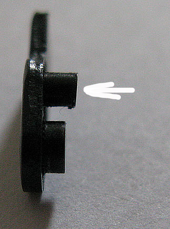
I don't have calipers, but the width of the worn "prong" is very approx. 2mm and the depth is also about 2mm. The level of wear as compared to the front ratchet must be less than 1mm! But enough to make it unreliable.
Posted by Andrew Woodcock (Member # 3260) on March 24, 2015, 05:52 AM:
Rob i am in work till 8pm but will get back to you later on this.
looks like it will be an easy repair though if i am seeing it right on my tiny phone screen.
[ March 24, 2015, 03:34 PM: Message edited by: Andrew Woodcock ]
Posted by Rob Young. (Member # 131) on March 24, 2015, 06:58 AM:
Andrew, when you get a chance, what is the best email address for Wittner do you think?
I'll see if they have replacement parts.
Posted by Paul Browning (Member # 2715) on March 24, 2015, 07:52 AM:
Hi Rob, good clear pictures mate, ok, the pin provides the drive in one direction, and slip out of the hole to allow it to travel in the opposite direction. The pin is warn at an angle, which is warn so much that its longest point from the base cannot now latch at the lower part of the hole, so riding up the angle and slipping, does this sound right so far?, can you determine which way round it travels, in relation to the pin angle.
Posted by Rob Young. (Member # 131) on March 24, 2015, 08:45 AM:
Hi Paul, I believe the worn part is supposed to fit through the hole on part 18 all the time.
In reverse mode, this holds the pin one way, so that the ratchet itself is out of an engaged position.
In forward, the hole pushes the pin the other way so that the ratchet swings to engage position.
So it is supposed to be always protruding through and engaging with the hole on part 18, regardless of direction; just swinging one way or the other.
It has clearly been allowed to rotate around disc 18 and wear down; possibly by coming out of position during rewinding.
"The pin is warn at an angle, which is warn so much that its longest point from the base cannot now latch at the lower part of the hole, so riding up the angle and slipping"
Yep, sounds right. It just about protrudes enough, but is now worn so much as to just about catch the sides of the hole on 18, but keeps slipping.
Posted by Paul Browning (Member # 2715) on March 24, 2015, 12:10 PM:
Hi Rob, does this just allow the rear arm to take up and allow the front arm to rewind ?, that it !!. No adjustment to take up tension, or clutches and springs. I can see there is just a hub its fixed to, and the spindle drives the toothed gear for the belt, and this clutch has the "D" shaped drive through it. Did you get any response from Wittner yet?, I wonder what the cost is going to be and what parts are included.
Posted by Rob Young. (Member # 131) on March 24, 2015, 12:45 PM:
Paul, as I understand it that is all these parts do, ie. make sure the ratchet is engaged or not engaged.
They are held under tension by part 17, which is just a spring.
Take-up tension is adjusted by adjusting part 2 in the rear of the machine; which increases or decreases the tension on spring 3.
When load is increased or decreased on the take-up spindle, it is handled by the slipping friction washers.
Unless I'm seeing this all wrong!? Which woundn't be the first time..lol...
Posted by Paul Browning (Member # 2715) on March 24, 2015, 02:01 PM:
Rob, that's how I see it mate. Looks too over engineered to do what its doing, for sure. OK here's my thoughts on this, if it was my projector and I was faced with seeing this, I would modify the driving gear first, and if space would allow fit the one way roller bearing that the GS uses in there, modify the spindle slightly, give it a plain shaft, not with the flat drive on it,( as its not needed), use the retaining circlip to hold it in place. Fixing the bearing to the gear would allow to lock in clockwise directing to take up, and free wheel to rewind. This works very well on the Elmo, yes I know the gear attached to it splits, but the bearing works faultlessly otherwise, and its doing the very same job, as this over complicated mechanism does. What you think Rob, its an alternative to what's coming at you from wittners ?. I've now measured the clutch bearing that fits the Elmo, although smaller in diameter this would fit into the existing toothed gear at the back of the beaulieu, depth is also good, would need to sleeve up the roller bearing to approx. 14mm to fit good, just the shaft bit now, will measure and get back on here. May not need to modify this shaft with the flat on after all, now will the roller take the extra torque and inertia from those big reels ?, maybe.
[ March 24, 2015, 03:28 PM: Message edited by: Paul Browning ]
Posted by Andrew Woodcock (Member # 3260) on March 24, 2015, 03:29 PM:
Hello again Rob,
If you are wanting to request original spares the website address I used to do all of my ordering and enquiring was,
Service@wittner-Kinotechnik.de
I would exhaust that avenue first if this was my machine.
There are easy ways to repair the Ratchet mechanism I think, if I am seeing it correctly, but if it were me, I would just want new exact parts to replace the worn and damaged ones with first and foremost.
Then I would have a go at carrying out a repair on what you have if the first choice isn't an option.
Finally as Paul says, fitting a "Formsprag " clutch arrangement in a modified shaft arrangement is certainly a possibility but for me, this is not a common enough fault on these projectors to justify any lack of trust in the original set up.
It just appears that at some stage the spring tension has been lost or forced back into its completely compressed state on the Ratchet Support Plates and therefore a gap has been allowed to form in between the normally sandwiched plates. This would then allow the Ratchet itself to become dislodged from its otherwise reliable location hole and travel slot in it's normally forced together, sandwiched state.
Also remember that these parts along with the others along the shaft form a dual function mechanism.
Yes it is a one way ratchet mechanism but because of the springs and friction washers etc, it is also a clutch. On any "fixed" method of drive, something has to give if the clutch becomes overloaded so as not to burn out the motor or cause damage to the inner gear mechanisms.
With this in mind, these original parts may just be the safest way to protect the rest of the mechanism in cases of the clutch being overloaded, for example film cleaning during rewinding etc etc.
Finally Rob, what is the condition of the screw 2.5 dia x10mm lg item 14 mounted to item 13, which I believe is what the ratchet engages with as it protrudes through the hole on item 18 when assembled correctly?
[ March 25, 2015, 10:42 AM: Message edited by: Andrew Woodcock ]
Posted by Paul Browning (Member # 2715) on March 24, 2015, 04:12 PM:
Hey Andrew, just noticed something on my beaulieu, its got the digital counter on it, LCD looks like. I thought it was like the Elmo with speedo type numbers in a line.
Posted by Andrew Woodcock (Member # 3260) on March 24, 2015, 04:20 PM:
They are usually only fitted to the Studio models Paul (93 onwards). Could this be what you have perhaps?
Posted by Paul Browning (Member # 2715) on March 24, 2015, 05:05 PM:
Sadly no LED's or spindle's changed. I wonder how easy it is to change the VU'S for the LED'S, it just look's like a plate has been put over the meters with the holes in, just four wires to the VU'S to connect up maybe ?.
Posted by Andrew Woodcock (Member # 3260) on March 24, 2015, 05:12 PM:
So what model was it originally Paul? Does it still have V.U. meter (s) ???
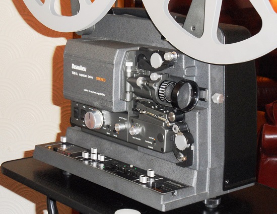
This is mine, is it roughly the same with LED's instead of V.U's?
Posted by Paul Browning (Member # 2715) on March 24, 2015, 05:54 PM:
I still have the vu's, slider knobs are smaller round ones, but I have LCD'S counter, maybe the original owner was upgrading it slowly, perhaps the change to the LED'S was too much at the time. I think they give a nice update to the vu's, which look a bit old hat, there more responsive too.
Posted by Andrew Woodcock (Member # 3260) on March 24, 2015, 06:01 PM:
Yes it sounds like it Paul.
So it's a Stereo model then Paul is it?
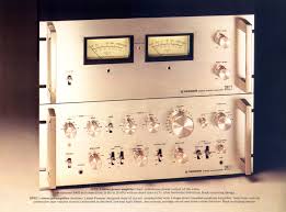
I use my Numark CM200 mixer with mine Paul so if I want, I can have LED's in use, however I just love the Old Retro V.U. meters and I am still searching for a decent 80's Pioneer class AA amp for mine when using it independently.
Part of the attraction is just those huge illuminated graceful V.U. meters Pioneer used to use. Just fantastic to an old 80's Old Romantic like me! Ha ha.
Something like this would be rather nice I suspect on the bottom tier of my projector stand:
[ March 25, 2015, 10:39 AM: Message edited by: Andrew Woodcock ]
Posted by Andrew Woodcock (Member # 3260) on March 25, 2015, 10:01 AM:
Let us know what you are deciding to do with this please Rob.
Brand new spares from Wittners, repair of existing parts or modification of the drive mechanism?
Also Rob, any news on part number 14 as spoken about a few posts back?
Posted by Rob Young. (Member # 131) on March 25, 2015, 01:00 PM:
Will do; I'm going to contact Wittner but work is in the way!
Will let you know the outcome.
Remind me about part 14??
Posted by Andrew Woodcock (Member # 3260) on March 25, 2015, 04:36 PM:
Look at what i wrote on march 24th 03:29 please Rob. It concerns part 14
I have to say Rob,that having looked at your photo's a few times over as well as the exploded view drawing from the manual, that if parts 14 and 21 all appear unscathed, if you just filed the worn pin flat and chambered the top edge on it again slightly,I see no reason why when re assembled correctly again with the correct spring tension re applied, why this assembly would not function perfectly well again.
If the Ratchet screw (14) protrudes through the hole on the plain ratchet plate as it should by around 6 to 9mm I am guessing, then the two pins on the actual ratchet are still in tact, only the moving pin not the pivot pin has wear to it and even then, fractions of a mm just to one side.
So long as it protrudes sufficiently to fill the curved slot to its full depth, and it appears it would, then it is doing its job in just the way it was designed to do so.
It appears to me, just from looking at the photos that once item 14 enters in between the two sandwiched ratchet plates, the entire mechanism should work as intended.
Let me know your thoughts on this Rob please and also please update me on the condition of parts 14 and 21.
On your first photo Rob, showing the Ratchet Support Plate and the Ratchet assembled together, the Ratchet Support Plate appears to be the opposite way around to the drawing as though the Ratchet itself (18) should be mounted into the plate from the opposite side. Is this correct Rob and if so, why have you photographed it with the Ratchet in the support plate the wrong way around?
[ March 26, 2015, 03:48 AM: Message edited by: Andrew Woodcock ]
Posted by Rob Young. (Member # 131) on March 26, 2015, 05:10 AM:
Andrew, the moving pin is worn in overall length AND at an angle,
So it just engages, but not enough.
It needs replacing I'm afraid.
There was some grease build up between the two ratchet supports which probably helped it slip out of place upon rewinding.
That and a gentle stretch of the spring is needed to provide a little more pressure.
Part 14 appears to be a screw which doesn't affect the ratchet or the two supports?
All parts are the correct way around as disassembled.
Posted by Andrew Woodcock (Member # 3260) on March 26, 2015, 05:14 AM:
Oh ok Rob,but can the pin not be straightened perhaps? If not it can be filed flat and then drilled and a new pin fitted, if you cannot obtain new from Wittners.
Also as I am seeing the drawing, it appears item 14 (the screw) is what engages with the Ratchet pin through the hole of the otherwise blank support disc in order to drive the back disc and then the hub spindle eventually.
Is this incorrect?
If so,
A/ What job does the screw do?(item 14)
B/ What does engage with the actual Ratchet (18) if not the screw?
C/ What is the solitary hole for in the otherwise blank Ratchet Support Disc?
As I say Rob, this part of the machine is something completely new to me as I have never had reason to investigate any section of either the front or rear drive clutches or indeed, Ratchet mechanisms so far, so I am learning all the time with this one.
Also Rob, if you look again at the drawing, I am certain it shows the disc and ratchet the opposite way around to your photo.
From the drawing the long part of the centre tube and bore with the flat on it points out whilst the ratchet is on the inside of this same support plate.
Your photo shows the tube with the flat on it, on the same side as the ratchet (18) not as opposites as the drawing suggests.
Posted by Rob Young. (Member # 131) on March 26, 2015, 05:28 AM:
Me too!!
It seems part 16 drives support 19.
Turning forward, this pushes the ratchet pin (the worn bit) against the hole in the other ratchet supprt (18) and thus it engages and drives 23 to provide take-up.
In reverse, 18 pushes the ratchet pin the other way to disengage 23, so it does not turn.
Hope that makes sense!!
Posted by Simon McConway (Member # 219) on March 26, 2015, 05:42 AM:
I have a clicking sound every one second on mine. Any advice?
Posted by Andrew Woodcock (Member # 3260) on March 26, 2015, 05:44 AM:
I am off in a couple of days so I may just have a look inside mine just to gain a better understanding of the situation.
If the Ratchet fits between the two support plates, then my theory stands up I think, however if the Ratchet fits on the outside of the last plate (the drawing does not make this 100% clear), then I can see what you are saying Rob.
I guess I will just have to see for myself as I will need to know at one time or another just how these parts fit and work together.
I am still no better off at this stage in understanding what the 10mm solitary screw does if it has no part to play in the Ratchet mechanism. It appears to me that the only thing it can do is come through those plates when assembled via the hole.
It is after all 10mm long??
BTW They all do it Simon, I think its the Ratchet mechanism, whichever one is "passing over" so to speak.
In other words, not the driven spindle at the time.
Or at least I did until this morning! Ha ha
Back to topic:
Either way by the time I have gone inside mine, I can take a detailed drawing of the Ratchet and get one or two made to have as spares or pass onto you Rob if you get no joy at Wittners with the Ratchet.
To me that is the only part that appears damaged enough to warrant replacement on yours Rob.
That shaft you mention Rob (16), appears only to have a flat on it at the very end to engage with disc 19.(again the drawing does not make this abundantly clear).
If this is the case there is nothing for the ratchet to bite hold of on the plain section of the round main drive drive shaft and make this ratchet mechanism work... following what you have seen during dismantling it from the way it was assembled??
Posted by Rob Young. (Member # 131) on March 26, 2015, 06:26 AM:
On the back of part 23, there is fitted a metal part with teeth for the ratchet to engage (not shown on diagram).
I'm sure it will become clear when you look for yourself, Andrew; I was hesitant at first but laid each part out in the order they need to be reassembled and actually, I don't think its that complex, although maybe not the most robust design...classic Beaulieu...
I agree, a new ratchet part would do for now.
Posted by Paul Browning (Member # 2715) on March 26, 2015, 07:47 AM:
The Elmo roller bearing idea would fix it, there is room for all the bits too, I wonder if Edwin could make that toothed wheel with the correct size for the clutch roller bearing ?, maybe. What's the part cost Rob, do you know .
Posted by Rob Young. (Member # 131) on March 26, 2015, 12:06 PM:
Had an automated email response from Wittner; they are closed until April 7th apparently.
I will try again then and see if they have the parts and at what cost.
Keep you posted!
Posted by Andrew Woodcock (Member # 3260) on March 26, 2015, 02:11 PM:
Thanks Rob and your last explanation makes.things a little clearer now thanks.
[ April 04, 2015, 08:48 AM: Message edited by: Andrew Woodcock ]
Posted by Rob Young. (Member # 131) on April 08, 2015, 12:02 PM:
Just an update as this may all be useful to other Beaulieu users in the future.
Wittner were very prompt in telling me that part 22, the ratchet is still available and the cost is 24.50 euro (plus a 4.50 euro surcharge for pats under 40.00 euro) with shipping to UK at 11.50 euro.
That plus 19% VAT and the total charge is 48.20 euro, or £36.52 pound sterling.
Not cheap, but thank goodness they have one and they are very polite, quick and helpful - something you can't always put a price on.
Sadly parts 18 and 19 (the ratchet supports) are no longer available as stock. However, they did say that they could possibly have them machined for me at a cost of 80-100 euros each.
Of course that isn't cheap either, but I just loved their enthusiasm (like many of the helpful forum members here) in even offering to have these made for me.
So, the ratchet is ordered and I'll post an update when everything is back together again.
Posted by Andrew Woodcock (Member # 3260) on April 08, 2015, 12:32 PM:
Hey, this is fabulous news for you Rob!! Cannot wait now until you report back to us all very soon now on a 100% perfect working beautiful Beaulieu as I am certain you will Rob.
Just go easy on that Red paint for the respray and please make sure you use no more than 2 gallon of WD40 to lubricate all those shiny new parts.
Joking aside..I actually think those prices sound quite reasonable by Wittners standards. The plastic spindles we both purchased for less than 100 euros (which is still extremely expensive) have rocketed to around 250 euros now I think when I last looked.
These machines have been described to me in the past by very reputable people within the industry as the Rolls Royce of Super 8mm projectors. At the price of the new spares nowadays from Wittners, it seems they are also comparing them to the luxury car manufacturer!
Posted by Paul Browning (Member # 2715) on April 08, 2015, 12:41 PM:
Could have got something sorted there rob, honestly mate, that's a lot of money for these simple parts, nearly £200.00 with p/p. I still think my suggestion with the elmo parts and the existing timing gear would work, and using that original gear, bearing is £3.25, Unfortunately they got you by the short and curlies, as polite as they are sadly.
Posted by Andrew Woodcock (Member # 3260) on April 08, 2015, 01:00 PM:
It all depends on how much you value the authenticity of these machines Paul. For me personally, I would always be very reluctant to use anything but genuine Beaulieu parts. The way I look upon it is, unless you do some scientific testing on any new design you implement, you just never truly know if this has a knock on effect on the rest of the mechanism in an adverse manner.
I have seen Robs machine on here and its a beautiful authentic example that appears very well cared for indeed. Therefore to me, Rob won't begrudge spending the money nor have any regrets I would have thought, once it is all working as per original design spec again.
[ April 08, 2015, 03:33 PM: Message edited by: Andrew Woodcock ]
Posted by Rob Young. (Member # 131) on April 09, 2015, 03:44 AM:
Hi Paul, I know what you're saying, but £37.00 isn't the end of the world if it fixes the problem, and to be honest, I'm no engineer, so if I can remedy this properly without huge cost then I'll be happy.
Of course, I would have to think very hard about spending 100 euros per part for the other components, but I think it will work without replacing them as they are just slightly worn as opposed to worn out!
Andrew has a point; I'd like to keep the projector within it's original design if I can because, well, I'm kinda fond of it!
But seriously, the take-up does need quite finite adjustment on this machine. Too much tension and it can possibly damage film at the start of a reel, by pulling the spring loaded guide roller too hard; the film can then touch the base of the lamp house. Too little and by the end of a 600ft spool, you have film sagging.
Basically, it's hard enough to get the tension right and consistent with Beaulieu's original parts, let alone start replacing them.
That said, thanks again to you guys for all your help and support with this.
I'll let you know the outcome when the ratchet arrives...it's on the way now...
And if it doesn't work I may just paint it red and use it for display purposes only!!
PS. Andrew, I saw the new prices for the spindles! Wow... ![[Eek!]](eek.gif)
Posted by Andrew Woodcock (Member # 3260) on April 09, 2015, 05:13 PM:
I'm kinda fond of that original design also!
Posted by Andrew Woodcock (Member # 3260) on April 11, 2015, 11:35 AM:
With regard to the spindle replacement parts mentioned above Rob, these have rocketed to 238 euros each after checking again.
I ordered mine for just less than 100 euros back in February 2014.
The problem is, if you want the original design with the two ball bearings fitted in each, you really have no other choice than to purchase them from Wittners.
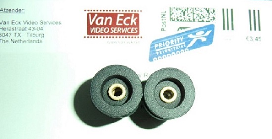
Edwin Van Eck now supplies very decent replicas for a fraction of even the price I paid in 2014, however as the photographs below show, there is a difference.
Edwin designs them as per original spec with a Sintered Bronze Sleeve Bearing as opposed to the uprated later designed Double Ball Bearing type as supplied by Wittners.
See photographs below,
First Wittners:
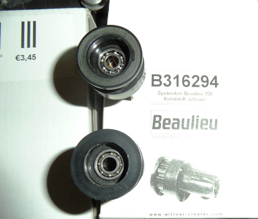
And then Edwin Van Eck 3D replica:
Posted by Rob Young. (Member # 131) on April 18, 2015, 03:25 AM:
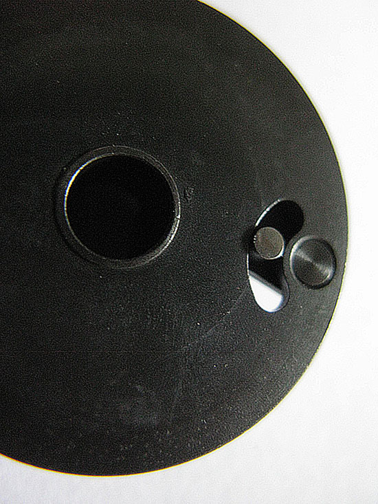
So the ratchet has arrived and seems to work, but the problem now is that I can't get the snap ring back on to hold everything together!
Here it is;
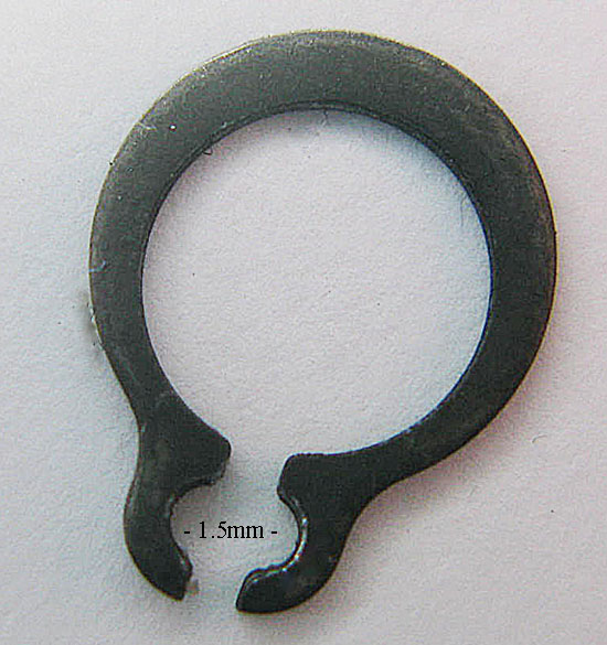
Problem is it is so small. The gap to stretch the snap ring open is les than 1.5mm and it simply will not go back on using small screwdrivers, etc. I've tried everything.
So I reckon I need some snap ring pliers, but micro ones that will fit this tiny size.
Problem is I've looked all over, including Maplins, but can't seem to find any small enough to do the job.
Any suggestions??
Posted by Paul Browning (Member # 2715) on April 18, 2015, 04:54 AM:
Hi Rob, The snap ring needs to open up to locate the larger ring to fit the groove in the shaft to hold all them bits in place?. Try this mate, get a drill just large enough to open the smaller hole, maybe a 2mm or 2.5 mm, carefully tap the plain end of the drill into the small hole on a flat surface, this will open larger hole maybe enough to get it in position over the slot in the shaft, obviously use the drill has an handle to hold this, once in position remove the drill, this will then snap shut in the groove, perhaps a pair of long nose pliers would be handy here, to hold the ring while you remove the drill, as it may fly off.
Posted by Andrew Woodcock (Member # 3260) on April 18, 2015, 05:10 AM:
Rob try Paul's excellent suggestion but If you want me to post you some snap ring pliers small enough to do the job, please just PM me and I could post you some or even pass them over to you today if you like..Then at least you would have a pair if you did more jobs in the future
Posted by Rob Young. (Member # 131) on April 18, 2015, 08:30 AM:
Paul, the problem is that the whole thing fits so snugly together that anything protruding means that you cannot get the darn thing in position...
Although, your drill idea gave me another idea! I twisted the plastic end of a pen top into the 1.5mm gap to open it up, then cut the end off and hey presto! The rear one is back on!!
BUT...the darn front one is a much tougher little devil and even with both us trying we cannot get it to open enough to snap over the shaft...grr...
Andrew, thanks so much for the offer! Too generous! Maybe if you could tell me where to get some micro clip ring pliers as I think it may be handy to have some for the future!
Posted by Andrew Woodcock (Member # 3260) on April 18, 2015, 08:47 AM:
Hello again Rob, the smallest decent set are SRP1a Snap On set. These have a closed tip gap of 1/16th of an inch which works out at 1.58mm. These are the smallest I have but they will just about fit the tiny snap ring you are fitting.
Also you can file the sides on any,even a cheap set to get the tips closer together.
There is an engineers merchants in A.U.l. that sells these small type pliers, or at least they did last time I visited them.
I will look up the name of the merchants and post it on here for you if you like. Otherwise just order a set of the ones mentioned above off the net. Snap On tools are top quality and will last you a lifetime in normal use.
http://www.192.com/atoz/business/manchester-m34/engineers-merchants/francis-kirk-socket-screws-ltd/47357b7349c15af143aa67a0efe291437fe75ad9/comp/
This is the merchant I was referring to Rob. Sorry they are classed as in Denton not A.U.L as posted but it is on the border of both. Hope this helps you.
[ April 20, 2015, 04:13 AM: Message edited by: Andrew Woodcock ]
Posted by Rob Young. (Member # 131) on April 22, 2015, 06:33 AM:
Thanks Andrew, although in a moment of inspiration (or desperation!, maybe) I remembered that we had a pair of small nail scissors in the bathroom with slightly curved, pronged ends.
Perfect!
Snap rings back on and a quick test...well, I'd also swapped the front ratchet support discs to the rear arm, as they were like-new.
Rear take-up working great!
Front ratchet...not! Just occasionally, you could here it slipping. So, took it apart again (groan) and gave the worn ratchet support disc a few coats of Hammerite Silk over the last few days, to build back up the worn surface.
Finally got it all back together this morning and all seems well! Hurrah.
For anyone taking these arms apart though, be really careful when reassembling them as they are so fiddly and precise.
Very pleased that the Beaulieu is finally up and running again, and at a cost of under £40.00, not the end of the world...although I don't want to see another snap ring in a very long time...lol...
Posted by Andrew Woodcock (Member # 3260) on April 22, 2015, 07:27 AM:
Nice work Rob and great improvisation may I add as we are all forced to do at times. The end result is all that matters and it appears you are the winner here Rob with such a small amount laid out for what otherwise would cost an arm and a leg at a recognized service centre. Very well done Rob!!
Posted by Rob Young. (Member # 131) on April 22, 2015, 11:26 AM:
Day off today, so after a clean up on the work bench, put the Beaulieu back in position and watched the fateful 600 footer of "Genevieve"!!
Ran beautifully, with perfect take-up tension throughout, smooth rewind and no unusual or worrying mechanical noises or glitches.
Success!
I can now reluctantly tell you anything you need to know about the Beaulieu arm assemblies...
Posted by Andrew Woodcock (Member # 3260) on April 22, 2015, 02:54 PM:
I am certain that will be invaluable information for all of us Rob at one point or another. Your results from this work is really encouraging to all of us who like to maintain our machines as far as we can. Once again, very well done Rob.
Posted by Rob Young. (Member # 131) on May 04, 2015, 05:24 AM:
Ran the first spool of "Raiders of the Lost Ark" on Saturday night...
That was the only reel as the capstan drive belt snapped!!
Filled out the Wittners order form this morning...
Thank goodness, in this day and age, people like Wittners are still going. They may be pricey, but invaluable!
Posted by Andrew Woodcock (Member # 3260) on May 04, 2015, 06:21 AM:
This belt and all the others can be purchased for less Rob (just for future reference). See the following for an example, Rob:- (OR9015)
http://www.ffr-film.de/index.php?page=antriebsriemen&language=de
Hopefully this will be the last chapter in your run of bad luck with your lovely projector for a long while to come now Rob.
[ May 04, 2015, 08:44 AM: Message edited by: Andrew Woodcock ]
Visit www.film-tech.com for free equipment manual downloads. Copyright 2003-2019 Film-Tech Cinema Systems LLC

UBB.classicTM
6.3.1.2