This is topic Record soundtrack from Agfa Sonector LS Super 8mm? in forum 8mm Forum at 8mm Forum.
To visit this topic, use this URL:
https://8mmforum.film-tech.com/cgi-bin/ubb/ultimatebb.cgi?ubb=get_topic;f=1;t=011686
Posted by Berend De Meyer (Member # 5856) on August 24, 2017, 09:29 AM:
After completing the scan of a reel, I transfer the soundtrack from a Super 8mm film to digital to import it in FCPX. For that purpose I use a Agfa Sonector LS Super 8mm sound projector and my ZOOM H4n digital sound recorder. For the connection between the two devices I use a DIN5 - projector output - to 3,5 mm jack - mic input.
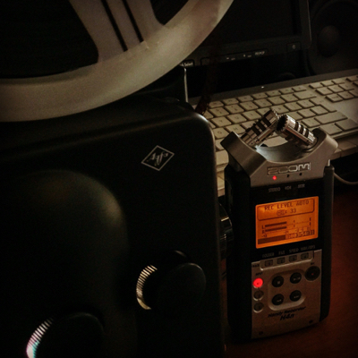
Q-1: why does this connection record what sounds like a mass (humming) issue noise, when recording a piece of film with no sound at all? I've set my ZOOM H4n to record with auto-level, because of all different scenes on the reel.
Q-2: I need a user manual to understand the in- and outputs on the projector, anybody knows a link to one online?
EDIT: Q-3: I used the Built-in Line Input of my Mac Pro 5.1, issue persists. How to troubleshoot this issue, could it be the mass on the projector?
Thanks is advance for your help.
[ August 25, 2017, 05:40 AM: Message edited by: Berend De Meyer ]
Posted by Berend De Meyer (Member # 5856) on August 25, 2017, 08:23 AM:
Using the EQ graphs I get this picture for the mass noise I just can't get rid of.

Posted by Andrew Woodcock (Member # 3260) on August 25, 2017, 08:32 AM:
Probably Berend, what you are hearing in the silent parts of any sound film you are attempting to transfer digitally, is the transformer noise being amplified through the magnetic heads and out from the amplifier through to the projectors loudspeakers and other auxiliary outputs.
Often recording directly from a Super 8mm soundtrack onto today's digital recorders produces no great results initially.
You may need to clean the audio afterwards using post production noise cancelling and noise cleaning software.
this is the kind of activity which our friend Janice here likes to get involved in rather than myself.
Maybe should could advise you better regarding her own techniques with this type of thing.
I spend far more time transferring digital soundtracks onto magnetic film rather than the other way around.
Posted by Berend De Meyer (Member # 5856) on August 25, 2017, 09:12 AM:
Hi Andrew, thank you very much for your quick and conprehensive reply. Very much appreciated. Yes, this is my very first workflow using this technique. I do indeed hope Janice could give me some directions, that would be great. Futher more I'll go check/read more about noise reduction and/or cancelling in post.
Have a great weekend!
Posted by Mike Spice (Member # 5957) on August 25, 2017, 09:17 AM:
try using a line input on your recording device.
Mic input will be too sensitive and the wrong impedance/level to accept the output from what I would assume is -10db line level from the DIN socket.
The 3.5mm input on your recording device will be stereo, where as I would imagine the output from your projector will be mono, so one side of the input is probably being shorted to earth.
The cable you are using, is that commercial or have you made it yourself?
Commercial cable will probably be wired for traditional stereo, and if your projector is mono, there lies the fault, along with using a mic input instead of a line input
In my case I take an output from the loudspeaker of my projector, through a small 'potential divider' and to the line input of my macbook and in to audacity using a custom wire I have made.
Soldered to the speaker terminals at the projector, through the resistors and then on to one leg of the 3.5mm jack in to my macbook.
I record a mono single track in audacity and then fix that in the edit to appear on L+R channels for playback
the fact this happens on your mac too points me straight to the cable. The mono output of the the projector and stereo input of your recording device is the crux of this issue.
one side is being shorted to earth and thus the hum
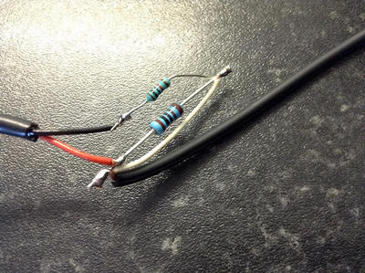
here is the wire I made to go from the projector speaker to the left input of my macbook. simple two resistors 10K and 100K
in audacity I record mono, and then copy and paste the recording to a second track, pan one track left, one track right and thus mono sound acorss the left and right in stereo playback.
I tried recording from my Eumig din socket with no luck at all as it turned out it was only an input for recording to the sound stripe.
Might be worth checking your din socket is actually an output and not just an input as mine is on the Eumig 905GL....
and here is an example of the audio I get. worth pointing out the jumps in audio are edits in the film and audio during the first sync test in my video edit
8mm sound from projector speaker with my wire
to save you the bother I can confirm one of your DIN sockets is an output, check you are using the output and not the input DIN socket.
I suspect the wiring of your lead is the issue here.
I have looked up your projector and I can see there is a DIN output but as I suspected, mono, and you are trying to go to stereo, so that is the problem here... one leg of the stereo is being grounded and almost certainly that is giving you the hum
Sonnector LS data sheet
I would always try to take the audio from a projector speaker output, I hate DIN plugs and the levels they spit out, if you are not up to soldering, perhaps invest in a small DI box to put in the signal chain between speaker output in mono and then in to your recording device.
I have a problem with Andrew's comment and I quote
"Often recording directly from a Super 8mm soundtrack onto today's digital recorders produces no great results initially.
You may need to clean the audio afterwards using post production noise cancelling and noise cleaning software"
I get great results and use nothing to to clean the audio from my super 8 as you can hear from my sync test link, that voice and audio was recorded in 1976 and still sounds amazing today
It is about the signal chain from a mono source to a stereo input at the right recording levels the correct signal levels and the right impedance.
As you point out Berend, your problem is humming, that is a direct result of a poorly constructed signal chain(mono to stereo, one side of the stereo input being shorted due to the mono source) incorect signal levels (mic input from a line output) and possibly using the wrong DIN connection on the projector
[ August 25, 2017, 12:24 PM: Message edited by: Mike Spice ]
Posted by Andrew Woodcock (Member # 3260) on August 25, 2017, 10:33 AM:
On the Agfa machine, the 5 pin din output socket will look a little like a letter Q just from memory.
Many sockets are dual function, input and output sockets but you need to check first on each and every model from it's manual to check it's functionality, otherwise you can do some damage to the electronics.
https://en.wikipedia.org/wiki/DIN_connector
Posted by Brian Fretwell (Member # 4302) on August 25, 2017, 04:35 PM:
Looking at that frequency graph it looks like peaks at 50, 150 and 250 hz which indicated a 50hz square wave (which is 50hz plus all odd harmonics, I used to work in Telex which has 25hz and used to take 300hz bandwidth to get a good signal with electro-mechanical teleprinters on long lines). I would suggest that mains frequency is being picked up and "clipped" somewhere due to it being too high a voltage to be passed as a sine wave. Is there an automatic gain control in the chain that might be doing this when there is no sound?
Posted by Berend De Meyer (Member # 5856) on August 26, 2017, 04:52 AM:
Hi guys, THANK YOU VERY MUCH for your overwhelming amount of info's and suggestions in reply to my questions. Greatly appreciated!!!
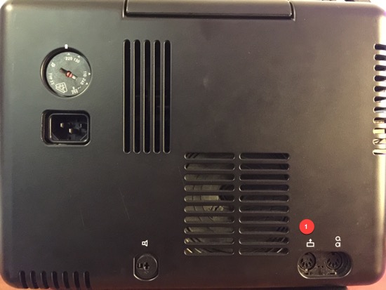
1. The output on the projector that I use
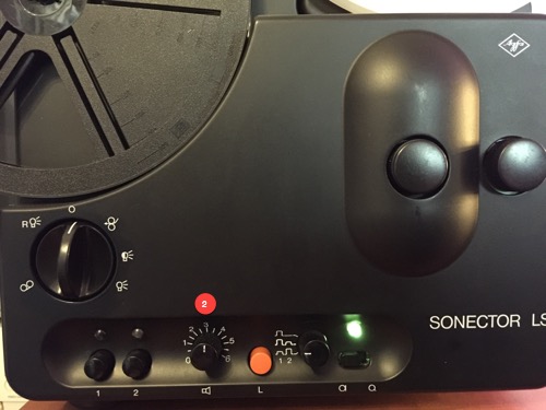
2. The knob I use to adjust the volume - mostly 3 - for the output going into the Built-in Line Input on my Mac and my post-production software.
3. I'll try to solder myself a new cable: DIN Speaker male <-> 3,5mm jack to try your solution Mike. This will be a totally new skill to teach myself, but hey, never to old to learn new stuff. ![[Big Grin]](biggrin.gif)
Mike, do I need more than just the two connectors and a piece of cable and do you perhaps have a wire-scheme / little DIY instructions for me? Your sound recordings of the Phantom Airplanes sounds amazing, thanks for sharing.
Posted by Andrew Woodcock (Member # 3260) on August 26, 2017, 07:13 AM:
The output din socket for feeding to your recording equipment is the rectangular box with the arrow from it sorry Berend.
The other one is for microphone input and external din input from a CD player etc etc.
There is a switch on the front fascia of the machine with the same two identical symbols.(Q & O with a flat line to the right).
You switch between the two depending on the chosen input, microphone or CD player etc etc.
Sorry it's been a while since I have looked at the back of one these but your photographs above just reminded me of the set up on these.
This same output 5 pin socket can of course be fed into a mixer or amplifier to gain a more powerful sound output from this projector than it ordinarily can provide from its own internal amplifier.
Nice little machine these. ![[Wink]](wink.gif)
Posted by Mike Spice (Member # 5957) on August 26, 2017, 10:11 AM:
Edit: further down the comments I have posted my hack for projector speaker to line in on your computer which I think is easier than messing about with DIN plugs.....
the easiest way to make your own 5pin DIN to mini jack cable would need a multi meter of some kind, a ready made DIN lead of some sort, as long as there is a DIN at one end, a lead with a stereo 3.5mm jack at one end.
Cut one end off the DIN plug to expose the wires and strip the insulation away and twist the wire up neatly on each of the connectors
Do the same for the 3.5mm jack
Pin 2 (the pin at 12 o clock) is the earth on the DIN lead and will be a screen wire in the lead.
Connect that to the screen lead of the 3.5mm, a soldered joint is best and wrap in pv tape.
Take the tip connection of the 3.5mm jack lead and connect it to (probably) pin 1 of the DIN lead.
do not connect the other conductor of the 3.5mm jack, cut it back so it cant touch anything.
making sure the wires are not touching each other at the joint, do a quick test to see if it is working. (there is no dangerous voltage to worry about in this lead so don't panic, just make sure no conductors are touching each other, other than the connection you are making)
If Pin 1 doesn't work try pin 4
Once you have established a working connection, then you can solder up your own lead properly, doing a quick twist and join is just to test to make sure you have the right conductors connected.
Using a multi meter you can use the continuity of the meter to check which wire is connected to which pin on the DIN plug and tip connector on the 3.5mm jack.
The projector is mono, so you only need the earth screen and the tip on the 3.5mm jack connected.
The tip connection on the jack, should appear in your recording software as the left channel.
In audacity I record a mono track, if I play this back on a stereo device it only comes out of the left channel. to get around that, I copy and paste the recording to a new track in the identical position as the original recording.
Then I pan one track left, the newly pasted track right, and export that as a wav to my video edit software.
I hope this makes sense, I am sorry I don't have a diagram, Google should be able to help you identify pin numbers for the DIN if you are stuck.
To sum up you need a connection thus:
PIN 2 DIN earth to Earth pin on the Mini Jack
PIN 1 (possibly 4) on the DIN to the tip of the mini jack
Only the earth and the tip should be connected in the mini jack.
It is highly unlikely but equally possible PINS 5/3 on the DIN could carry the output but by my experience it should be pin 1 for the + and pin 2 for the -
I hope this makes sense. good luck...
This is why I went for the speaker connection through my two resistors!
perhaps use youtube for a quick 'wire tinning' tutorial and soldering demo if you are unused to soldering
When I made my DIN to mini jack I was a little more daring, I had the DIN wire stripped back and connected to the projector, playing a sound movie, the 3.5mm connected to audacity, set to monitor audio, the earth lead connected through the audio cable, then touched each of the DIN connectors with the tip wire of the mini jack to see which pin gave out audio, that's when I discovered the DIN on my projector was only an input.
Obviously take care, there are no dangerous currents in a 5pin DIN and mini jack, but if anything touches anything that shouldnt touch, you will get hum or no sound and a short, as long as you are sensible you should be ok using my quick and dirty method, Once you establish the right connections, make sure the join is well insulated .. or make you own lead usiing a new DIN plug, Jack Plug and single screen wire.
Soldering 5 Pin DIN plug is not for the faint hearted or inepxerienced, it is very very easy to heat the pin too much and melt the plastic around the pin, and the plug is rendered useless in a second, which is why I suggest taking a ready made din, and using one end of it to connect to the mini jack...
For a 5 pin din plug I would not use a soldering iron hotter than 15 watts
[ August 26, 2017, 01:30 PM: Message edited by: Mike Spice ]
Posted by Andrew Woodcock (Member # 3260) on August 26, 2017, 10:25 AM:
Din connection idents are in link I posted earlier.
Posted by Mike Spice (Member # 5957) on August 26, 2017, 10:30 AM:
it depends on whether the projector audio has been deemed 'an amplifier' or a 'tape recorder' the pin wiring is different.
I have seen cases where the magnetic stripe has made the projector effectively a tape recorder for the DIN wiring, and another case where it's pins were set up as 'an amplifier' depending on what region the machine was manufactured...
Posted by Andrew Woodcock (Member # 3260) on August 26, 2017, 10:40 AM:
The projector was made in Germany by Bauer and i think from memory the connections were as standard.
Posted by Mike Spice (Member # 5957) on August 26, 2017, 11:42 AM:
if you want to go the speaker output route (which I think is much easier) you will need some two core speaker wire and some single screen audio wire and two resistors, 10k and 1k, (half a watt or 1watt will be fine) a speaker plug and a 3.5mm jack plug
I used a pre made 3.5mm jack lead and cut one end off.....
Use a meter set to continuity to determine which wire is connected to tip, and use that, cut the ring connection back out of the way as I have.
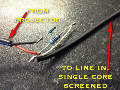
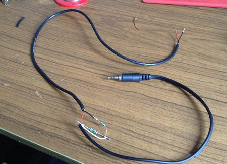
on the computer end, the screen is connected to the earth of the jack, and the positive to the tip of the jack.
In this photo you can just make out that one of the two wires on the moulded cable in to the mini jack has been cut back and not used (the ring connection) I used a pre made lead and cut one end off to save me soldering the 3.5mm end as I am lazy!
I have made an error in this, the black and red wire from the projector are soldered to the resistors the wrong way around, so I used the red wire as neg and black as positive at the projector end, to save me re soldering the resistor end... hope that makes sense.
begin with the projector volume at around quarter volume and increase as you see fit.
here is the circuit diagram
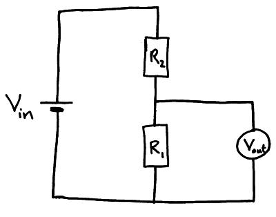
V in being the projector speaker
V out being the connection to the computer, the positive(tip) connection coming from R1 ( R1 1k ,R2 10k)
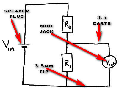
R1 1k ,R2 10k
This circuit was given to me by a very knowledgable chap in the audio facebook group I run, it worked brilliantly so thanks to him, you can also find plenty of info about 'potential dividers' in google
My Eumig didn't have a speaker socket, so I soldered on to the speaker
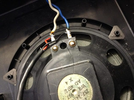
you can see from my bodge, I have left my wiring exposed, it is entirely up to you how you make this and insulate it, I chose not to, it's quite safe as long as nothing shorts out, but it would be better practice to insulate exposed wires even tho' it is only a line level....... I am lazy, it worked, I am happy....
when soldering resistors, apply the minimum amount of heat so as not fry them, I would not use an iron hotter than 25w, I used a 15w iron for mine. You could also use nose pliars to grip the resistor wire by the resistance bit, to act as a heat sink as a precaution if you wanted to.
The shorter the wire from resistor to line in, the less chance of hums and interference.
You might not be able to see in my resistor photo, closest to the camera, the black lead for the input to computer, the screen of that cable is soldered to the end of the resistor wire, while the white comes along the resistor to the other end, I cut this tight on purpose so the screen of the wire could not touch anything else in the circuit.
[ August 26, 2017, 03:02 PM: Message edited by: Mike Spice ]
Posted by Berend De Meyer (Member # 5856) on August 26, 2017, 06:36 PM:
Mike and Andrew, thanks again for all your replies. I really need to process and digest all your info's here.
Mike, as I have the Agfa Sonector LS as a full original boxed item, I don't have the nerves to mess around inside the projector and/or speaker housing. I'll just focus on buying / making a cable just for this purpose alone. As said earlier, soldering isn't my 1st let alone 2nd nature, so I'll stay on the BIY cable route for now. ![[Wink]](wink.gif)
Keep you posted on my further quest for solving my line-in noise issue on the hardware side of things.
I also tried to use a NoiseGate trying to eliminate the noise, but that disrupts the sound recording in such way that itís a no-go for me.
Iíve been asking around in a HiFi group on Facebook and someone nearby the place where I live is willing to make me a cable with a ďgroundloop isolatorĒ. It seems that because I have a house with ALL ground-shielded powerplugs this could be the root of all bad.
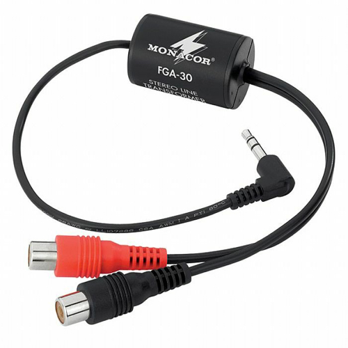
So for now Iíll try some options with the cables I have on my desk / in my locker. Otherwise Iíll ask the good fellow to make me one.
Again thanks you both for all your time and effort to help me solve my problem. Keep you posted on the outcome of my cable experiments.
Posted by Mike Spice (Member # 5957) on August 27, 2017, 02:15 AM:
the ground loop isolator is a great little tool, but again, you will only use the tip connection on the jack.
Using the device in your picture, you then just need an rca phono plug wired to the correct pin on a DIN plug with a length of single core screened wire..
I wasn't suggesting you open up your projector, I can see you have a speaker DIN plug which makes things easier in your case.
Noise gates can be useful, but if the attack and releases are not set correctly then they will not perform well.
You would want a fast attack, so the gate closes when there is no audio, but if you have a lot of hum at a similar level to the audio, the gate will not be able to distinguish between what is wanted audio and unwanted noise...the threshold setting determines that aspect of things.
A noise gate is usually used on something like an electric guitar or microphone, when there is no audio, the gate closes the signal path, so no stray noises appear in the mix
[ August 27, 2017, 06:28 AM: Message edited by: Mike Spice ]
Posted by Berend De Meyer (Member # 5856) on August 27, 2017, 04:49 PM:
Mike, the issue is in the projector itself. I never heard it before viewing a S 8mm film with sound on the projector itself. But only after the 1st recording session it became audible with my headphones HD 650.
Here is the video on YT for this issue:
https://youtu.be/v2y0HIgQfz0
Tomorrow I'll call Van Eck Video (NL) to aks them to elaborate my options. Keep you posted on the outcome. Thanks again for your time and sharing all your knowledge. Greatly appreciated.
Posted by Mike Spice (Member # 5957) on August 28, 2017, 04:46 AM:
I have watched the video, but have no idea what would cause the projector to make that noise as you increase the volume.
Posted by Berend De Meyer (Member # 5856) on August 29, 2017, 08:32 AM:
I called Van Eck, 99% probable cause is the power supply. So that needs to be fixed. BUT I have some great news about solving my issue. There's a tweak in FCPX "Hum Removal: that eliminates the noise for 50Hz or 60Hz! ![[Big Grin]](biggrin.gif)
Great tip I got...
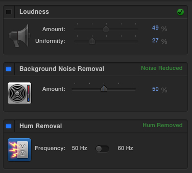
So I can call this case closed!
Thanks everyone!
Visit www.film-tech.com for free equipment manual downloads. Copyright 2003-2019 Film-Tech Cinema Systems LLC

UBB.classicTM
6.3.1.2


![[Big Grin]](biggrin.gif)
![[Wink]](wink.gif)


![[Wink]](wink.gif)

![[Big Grin]](biggrin.gif)
