This is topic Pathescope 9.5 200B in forum 9.5mm Forum at 8mm Forum.
To visit this topic, use this URL:
https://8mmforum.film-tech.com/cgi-bin/ubb/ultimatebb.cgi?ubb=get_topic;f=9;t=000117
Posted by David Lingard (Member # 2323) on November 29, 2010, 03:34 PM:
I have a 200B projector which was working perfectly till I decided to rewire the voltage dropping resistor. As I unscrewed the contacts of the 3 pin plug the wire fell out corroded and the insulation was brittle. I am trying with little luck so far to work out which wire goes where. With the Resistor switch connected to end contact that connects to the direct link in the projector's base compartment. The other end of the resistor (connected to the 240V pickoff) goes to the other end prod of the three. The motor runs but there is no voltage available to the lamp. Connecting the dropped voltage wire to the centre prod which goes to the lamp, blew my only (probably expensive) lamp. The motor uses between about 11 to 20volts depending on speed. Nothing approaching the 115V for which it is rated. How do I get 115v to the lamp - and for that matter get another lamp in the UK?
Can anyone help please? e.g. image of a correctly wired plug perhaps? or a technical manual? Or just a description!
Posted by Dino Everette (Member # 1378) on November 30, 2010, 01:49 AM:
David, I'm trying to figure out your post, is your plug to the mains what you were rewiring or the plug that connects the resistance to the actual projector? If you let me know i can probably take some pics for you so you can correct the prob..
Posted by David Lingard (Member # 2323) on November 30, 2010, 12:33 PM:
Thanks for your rapid response, Dino. It is the three pin plug of the voltage dropping resistor that I am trying to rewire. At present I have the switch on the resistor connected to the pin that connects to the 240V live socket (as ascertained from the junction box in the bottom of the projector), the pin at the other end is connected to the 240V pick-off of the resistor (that is the max resistance of around 68 Ohms) and the centre pin is (now!) not connected to anything! I tried it also connected to the 240v pick-off which has on it the dropped voltage but that is what blew the bulb. But.....that still seems the logical connection as the centre prod does connect to the supply to the bulb in the projector's junction box. What say you? My projector motor still runs quite happily. I am surprised that you have a resistor as according to my booklet that goes with the projector, it is only needed for voltages above 115 volts and that is what you use in the US of course. Thanks again and I look forward to hearing from you. Regards, David
Posted by Dino Everette (Member # 1378) on November 30, 2010, 03:48 PM:
David
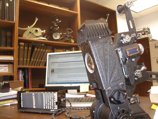
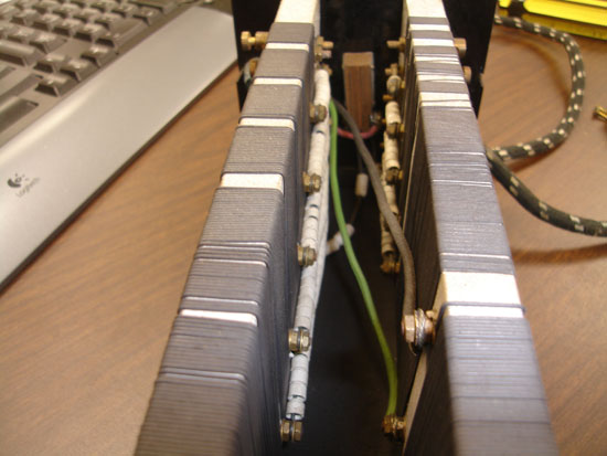
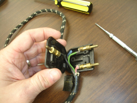
I took some pics but won't be able to post them until I am back at home this evening, when of course you will be sleeping, but the way it seems is actually more logical than I thought..As far as the resistance goes, if you are looking at it from the end without the switch the block on the left is for the lamp(which is tied to the switch) and the wire from it should go to the far left pin (It has a larger gap between it and the next pin over making it actually sort of off by itself)...The other 2 wires are coming off the block on the right are designated for the motor and they correspond to the middle and right pins on the plug as follows: The one attached high on the resistance block goes to the middle pin, and the one low on the block goes to the far right pin...Mine are colored as follows:
left pin - red wire
center pin - black wire
right pin - green wire
Let me know how you make out, but I'll post the pics regardless..
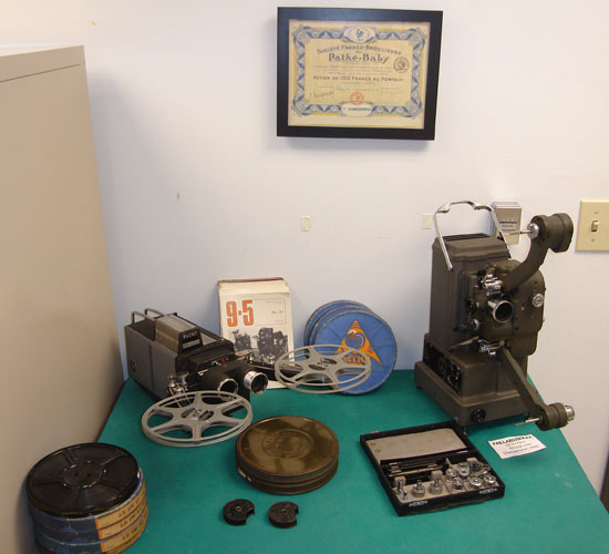
PS couldn't resist adding a couple of my office to show that 9.5 is proudly represented to all who enter.
Best
dino


[ December 01, 2010, 12:09 AM: Message edited by: Dino Everette ]
Posted by Peter James Diggle (Member # 1533) on December 04, 2010, 01:58 AM:
I have a 200B bulb left from a conversion to QI> Free if we can arrange transit.
Posted by David Lingard (Member # 2323) on December 09, 2010, 09:55 AM:
Dino,
Many thanks for that comprehensive reply. Life has been rather hectic in the past week - as usual for retirees there is too mnch to do and too many organisations that demand time! Especially around Christmas. Anyway, I will make time to try to match what you show with my setup over the next few days. My first reaction is that my resistor doesn't look quite the same, but closer scrutiny may show why or how. I'll keep you in the picture. Your workshop setup is most impressive - and nice and warm! My workshop contains a recently rebuilt vintage (1930) Sports car and is mighty cold at present.
Regards, David
Visit www.film-tech.com for free equipment manual downloads. Copyright 2003-2019 Film-Tech Cinema Systems LLC

UBB.classicTM
6.3.1.2


