8mm Forum


my profile | my password | search | faq | register | forum home
  next oldest topic   next newest topic
» 8mm Forum   » 8mm Forum   » GS1200 Capacitor Swap Help!

 - UBBFriend: Email this page to someone!    
Author Topic: GS1200 Capacitor Swap Help!
Burton Sundquist
Master Film Handler

Posts: 318
From: Burnaby, B.C. Canada
Registered: Feb 2017


 - posted January 23, 2019 08:15 PM      Profile for Burton Sundquist     Send New Private Message       Edit/Delete Post 
I installed a new capacitor to replace the original C172 in my GS1200. As careful as I was it looks like I have created 2 solder bridges. Looking at the back of the board, where the top terminal is, solder is touching the terminal to it's right.
These two points appear to be part of one printed circuit but need advice. The same thing happened at the bottom terminal.
solder is touching the terminal beside it to the right. These terminals appear to be part of another printed circuit. I would appreciate advice on this.

[ January 23, 2019, 09:32 PM: Message edited by: Burton Sundquist ]

 |  IP: Logged

Burton Sundquist
Master Film Handler

Posts: 318
From: Burnaby, B.C. Canada
Registered: Feb 2017


 - posted January 25, 2019 08:25 PM      Profile for Burton Sundquist     Send New Private Message       Edit/Delete Post 
...Anyone? I tried to de-solder it but there is still a trace of solder connecting the top capacitor terminal to the terminal on its right. Same on the bottom.

[ January 25, 2019, 10:37 PM: Message edited by: Burton Sundquist ]

 |  IP: Logged

Graham Ritchie
Film God

Posts: 4001
From: New Zealand
Registered: Feb 2006


 - posted January 26, 2019 03:41 AM      Profile for Graham Ritchie   Email Graham Ritchie   Send New Private Message       Edit/Delete Post 
Burton

You need to buy a "de-soldering pump" they are cheap to buy at most electronics suppliers . Can you post some photos? If in any doubt about soldering, I would suggest finding someone to do it for you. If not be very careful not to apply heat in any one spot for to long.

 |  IP: Logged

Burton Sundquist
Master Film Handler

Posts: 318
From: Burnaby, B.C. Canada
Registered: Feb 2017


 - posted January 27, 2019 12:43 AM      Profile for Burton Sundquist     Send New Private Message       Edit/Delete Post 
Graham, So happy to hear from you and Thanks for replying. Terrible photo just like the soldering job. I sucked up the extra solder that made the bridge but there is
No way of getting rid of the trail from the top capacitor post to the other terminal. To me it looks like it should be part of the same circuit? Or am I out to lunch ( stupid ). Same with the bottom solder. looks like another blunder. I wlll try once more heading your advice about overheating the board. Thanks again.
 -

 |  IP: Logged

Phil Murat
Jedi Master Film Handler

Posts: 671
From: Villeneuve St Georges, France
Registered: Dec 2015


 - posted January 27, 2019 05:19 AM      Profile for Phil Murat   Email Phil Murat   Send New Private Message       Edit/Delete Post 
Hi Burton,
I suggest you to use small soldering wire, 1mm diam, special electronic with resin included.
To prevent from sensible components overheat' maxi soldering time is approx 3 to 5 sec.
Soldering iron with narrow tip showing 20 w is ok, 10w with batterie is good for soldering chips or very sensible components.
a solder is considered to be satisfactory when it appears shinny and well collapsed. A ball appearance is not good.

As Graham said, a desoldering pump is a necessary investment. I use also Copper mesh depending on the situation.

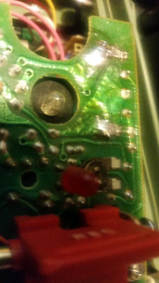
Is it possible to get more picture(s) for board concerned ?
If board is epoxy, this is a good news, as epoxy boards are stronger than former plastic or bakelite ones. Epoxy board are fibers reinforced.

What is the function of this board stage ?
Why did this capacitor failed (aging or overheat) ?

Try to train on scrapped electronic board showing different kinds of components to be more confident with that.
However, fusion soldering point on modern bords is higher than vintage assemblies

Let us know
Thanks

 |  IP: Logged

Leon Norris
Jedi Master Film Handler

Posts: 958
From: Elkins Park, PA, USA
Registered: Jun 2012


 - posted January 27, 2019 02:20 PM      Profile for Leon Norris   Email Leon Norris   Send New Private Message       Edit/Delete Post 
Don't worry Burt Because I have a few in stock! Just take your time. The amp assy. Comes in two parts! Hopefully you will do good. But if not then let me know! Thanks, Leon.

 |  IP: Logged

Burton Sundquist
Master Film Handler

Posts: 318
From: Burnaby, B.C. Canada
Registered: Feb 2017


 - posted January 27, 2019 02:57 PM      Profile for Burton Sundquist     Send New Private Message       Edit/Delete Post 
Thanks fellows, but the original question I have has not been answered. At the top, is the capacitor terminal supposed to be connected via printed portion to the terminal to its right?
Same question re: the bottom Capacitor terminal. Anyone with electrical knowledge of this board? Thanks...

 |  IP: Logged

Leon Norris
Jedi Master Film Handler

Posts: 958
From: Elkins Park, PA, USA
Registered: Jun 2012


 - posted January 27, 2019 03:18 PM      Profile for Leon Norris   Email Leon Norris   Send New Private Message       Edit/Delete Post 
What you need Burt is a good Desoldering tool. Like I got! Its a electric one. Its very strong. It sucks up that old solder in seconds! It does a great job! Good luck! Leon.

 |  IP: Logged

Renzo Dal Bo
Film Handler

Posts: 70
From: Mogliano Veneto, Italy
Registered: Dec 2016


 - posted January 27, 2019 03:20 PM      Profile for Renzo Dal Bo   Email Renzo Dal Bo   Send New Private Message       Edit/Delete Post 
Hi Burton,
maybe this thread can help you.

http://8mmforum.film-tech.com/cgi-bin/ubb/ultimatebb.cgi?ubb=get_topic;f=1;t=007889#000000

The capacitor is only a "bridge" connecting the two largest top right "islands" of the PCB and it hasn't any polarity to respect.

 |  IP: Logged

Burton Sundquist
Master Film Handler

Posts: 318
From: Burnaby, B.C. Canada
Registered: Feb 2017


 - posted January 27, 2019 08:48 PM      Profile for Burton Sundquist     Send New Private Message       Edit/Delete Post 
Thanks Renzo, Leon, Phil and Graham for all your Help. Board cleaned up and joints re-soldered. Test recorded and I know have full dynamic range on both tracks! I never knew such small stripes could produce audio of this Quality! Thanks again to everyone!

 |  IP: Logged

Paul Adsett
Film God

Posts: 5003
From: USA
Registered: Jun 2003


 - posted January 27, 2019 10:17 PM      Profile for Paul Adsett     Send New Private Message       Edit/Delete Post 
Congratulations Burton. Any time and energy that you spent on this modification will be well worth it when you listen to that stellar quality stereo!
I have yet to do this mod on my GS's, since I use my Eumig S938 Stereo for all re-recording jobs, but I really ought to take it on and get my GS up to full specs and performance. Exactly what capacitor did you use and where did you get it?

--------------------
The best of all worlds- 8mm, super 8mm, 9.5mm, and HD Digital Projection,
Elmo GS1200 f1.0 2-blade
Eumig S938 Stereo f1.0 Ektar
Panasonic PT-AE4000U digital pj

 |  IP: Logged

Burton Sundquist
Master Film Handler

Posts: 318
From: Burnaby, B.C. Canada
Registered: Feb 2017


 - posted January 28, 2019 12:29 AM      Profile for Burton Sundquist     Send New Private Message       Edit/Delete Post 
Hi Paul, Yes if you have the right tools for the task and work carefully it's a simple replacement and that is it. If need be you could also adjust the bias for each channel after swapping the capacitor. Not needed in my case as both tracks are in balance and produce full range.
Here is a link for the capacitor I used:

https://w ww.ebay.ca/itm/1pcs-PHILIPS-KS-3300P-3300pF-3-3nF-630V-1-Axial-Polystyrene-Capacitor/151664766262?ssPageName=STRK%3AMEBIDX%3AIT&_trksid=p2060353.m1438.l2649

...This was courtesy of Renzo. His sync box works excellent as I already synced a
DVD almost frame to frame on 800' reel. The sound is so amazing, particularly the balance stripe considering it's width.

And Phil, I wanted to answer your questions too. This capacitor is a recording component on the amplifier board
Known to fail after many years due to its proximity to a resister that heats up during recording. Some members have replaced the capacitor on the back side of the board for this reason. Thanks to everyone who was of help!

 |  IP: Logged

Phil Murat
Jedi Master Film Handler

Posts: 671
From: Villeneuve St Georges, France
Registered: Dec 2015


 - posted January 28, 2019 04:05 AM      Profile for Phil Murat   Email Phil Murat   Send New Private Message       Edit/Delete Post 
Thanks Burton for this info.

So, I have not replaced this capacitor on my machines yet.

However I understand this capacitor is working under high frequencies so that it overheats.

If there is room enough around preamp board I will not installed the same capacitor (3000pf / 630V , polystyrene),but I'll replace it by 2 x 1500pf or 3 x 1000pf installed in parallel to decrease impedance.(Polyester or polypropilene caps are supposed to work too).
By this way overheating has to decrease significantly.

 |  IP: Logged


All times are Central  
   Close Topic    Move Topic    Delete Topic    next oldest topic   next newest topic
 - Printer-friendly view of this topic
Hop To:

Visit www.film-tech.com for free equipment manual downloads. Copyright 2003-2019 Film-Tech Cinema Systems LLC

Powered by Infopop Corporation
UBB.classicTM 6.3.1.2