This is topic Amp Wiring advice for Sankyo 600 Switches -Motor in forum 8mm Forum at 8mm Forum.
To visit this topic, use this URL:
https://8mmforum.film-tech.com/cgi-bin/ubb/ultimatebb.cgi?ubb=get_topic;f=1;t=009360
Posted by Phil Mitchell (Member # 3876) on August 11, 2014, 04:57 AM:
Hi all,
Would I be right to say that as the micro switches the wires from the board power and negative would be 3amp as the switches are 3amp 125volt 2amp 250volt?
This is the wires that connect to the Micro switches.
The quality of wires I have to go between board and switches are quite poor, want to replace.
Excuse my lack of electrical knowledge but why are the switches 3am 125v and 2amp 250volt out of interest anyone know.
That is what is written on them.
One more thing how many amps does a Sankyo 600 motor or similar need to run?
Thanks in advance
Phil
Posted by Andrew Woodcock (Member # 3260) on August 11, 2014, 05:10 AM:
Hello Phil,
What is written on the side of the micro switches is just the rating of the switch and quite possibly no reflection of the actual voltage or current present within the particular circuit where the switches are.
Have you tried measuring the voltage present at the switch terminals?
You can also check the current draw from the motor circuit if you have access to a decent multi meter or better still a clip on ammeter.
BTW Phil you don't "feed" amps to make a motor run. Voltage is what is provided, and current is a measurement of the "flow rate" of electricity drawn on that particular circuit by the load, in this case the motor.
If you think of it as a Sink Tap then the voltage is the water pressure and the current is the flow rate of the water coming from the tap. This of course is dependent on the bore size of the pipe in the same way that electrical cable sizes increase as a circuit demands more current.
[ August 11, 2014, 07:04 AM: Message edited by: Andrew Woodcock ]
Posted by Phil Mitchell (Member # 3876) on August 12, 2014, 02:43 AM:
Hi Andrew thanks for reply.
I understand what you mean about Volts and amp with water example. Ta for that.
With my multimeter on 200m mille amps, I am getting a reading from power wire on switch and negative on switch of 00.81
Does this sound like enough power to run motor?
( I also get this reading when I push in switch plunger from the Com terminal, putting red tester cable to it instead of power one.
I tried putting MM to the 10amp setting which one has to swap red lead to the 10adc socket but I get no reading on that and testing leads started to get warm, so I stopped that straight away.
Seems to me switch is okay but the wiring to the circuit board that sits behind these switches where the two wires for motor run to terminals on other side of this board, I cannot get a good enough solder / connection as wires are quite brittle.
What type of wiring should I buy to replace what I have, I know not a lot about wiring gauges, Jaycar here in Australia which is like RadioShack in USA, has these hook up wiring, refer link, would that do?
http://www.jaycar.com.au/productView.asp?ID=WH3025
Thanks again
Phil
if I am getting 00.81 mille amps
Posted by Andrew Woodcock (Member # 3260) on August 12, 2014, 04:25 AM:
Sorry Phil, I am lost, is the motor actually running and if so how many volts are present on the actual motor terminals?
Though I have never owned your machine I believe it has a circuit regulated DC motor driving it.
Remember, with a multimeter, to measure current you have to measure it in series with the circuit so it can sometimes mean detaching a cable etc and fitting a temporary join. That is why I said using a clip on ammeter acting as a C.T. is far easier to actually use.
Always measure the voltage in parallel across the motor terminals etc.
Posted by Martin Jones (Member # 1163) on August 12, 2014, 06:47 AM:
Probably get slated for saying this .... but Phil, stop right there!
If you do not understand what you are measuring, why you are measuring it, or even how to use the tool you are attempting to measure it with, you might just as well be attempting to mend a watch with a sledgehammer.
It IS possible to guide someone through a repair remotely (I've done it more than once), but ONLY when the "Guider" has a thorough knowledge of the subject machine, can communicate CLEARLY what needs to be done, Step by Step,AND the "Guided" has basic measurement, mechanical and soldering skills, can follow instructions TO THE LETTER and CLEARLY communicate the results of what he has been told to do.
Outside of that,the world is full of scrap projectors and other devices as a result.
Phil, consult a competent mechanical/electronic hobbyist ..... or a professional repair specialist; there's at least one in Australia.
Martin
Posted by Andrew Woodcock (Member # 3260) on August 12, 2014, 07:45 AM:
Good advice Martin
Posted by Phil Mitchell (Member # 3876) on August 12, 2014, 11:28 PM:
Hi Martin/ Andrew.
No very good advice Martin.
There is a thread on here where Janice had a similar problem with a Snakyo of hers, someone helped her out in how to use a Multimeter, I am going to read that before I do anymore.
Also the orginal wiring for these switches etc I am going to replace, even if I was best soldering person, I doubt they would solder, my brother today suggested putting some terminals on wires to the micro switches, as where they sit in projector there is room above for terminals, would make job a bit easier.
And yes the motor is not running connected up, But it does run, I did the 9volt battery test to it alone, connecting the blue and white wires from motor to battery and we replaced the brushes in it.
Cheers
Phil
Posted by Martin Jones (Member # 1163) on August 13, 2014, 03:49 AM:
Phil,
The clue is in the statement ...
"I tried putting MM to the 10amp setting which one has to swap red lead to the 10adc socket but I get no reading on that and testing leads started to get warm, so I stopped that straight away."
If the leads which are INTENDED to carry 10 amps are getting warm, only God knows what excessive currents you have already subjected the projector circuits to, for how long, and what damage has ALREADY been done!
And ..... "No very good advice Martin". Is that "NOT very good advice, Martin" or is it " No, very good advice, Martin"?
That's where the "CLEARLY" part comes in!
Posted by Phil Mitchell (Member # 3876) on August 14, 2014, 12:44 AM:
Martin, actually shouldn't it be
Yes that is very good advice.
Anyway to quote what someone instructited Janice in another rpost on this ofrum about how to use a MM etc. Correct me if this is wrong, bit the below makes sense to me.
"The meter dial goes to "200" in the section "DCV"
You take one lead and touch one terminal (and only the terminal!), take the other lead and touch it only to the other terminal. The only difference flipping them makes is one way the number will have a minus sign, the other it will not.
You should see zero(ish) when you expect the motor to be off. You should see something (12V, 20V, 24V?) when it's supposed to be on.
Best way to do it is carefully connecting up using leads with alligator clips or EZ hooks, but one way or the other be careful and respect that metal motor case! Shorting to it can cause grief you didn't start out with."
I have Alligator clips to connect to MM prods to use, get a more reliable connection and of course safer.
Cheers
Phil
Posted by Martin Jones (Member # 1163) on August 14, 2014, 02:53 AM:
Yes, Phil.
You followed those correct instructions .... then for some reason (known only to yourself) you followed them again using the 10 amp range!!!!!!
You were NOT told to do that, which is what I meant by following instructions TO THE LETTER. What you did was to effectively put a dead short between the measuring points and invite the projector to put out more current than it was intended to from that part of its circuit ... and it did; enough current in fact to warm up the leads on the Multimeter, which are designed to run cool at all normal usages.
Multi-meters are very useful tools when used properly..... but then, so are sledgehammers.
I repeat what I said before..... "If you don't understand what you are doing, don't............"
End of lecture, I'm out of this topic.
Martin
Posted by Phil Mitchell (Member # 3876) on August 17, 2014, 06:00 AM:
Thanks again Martin.
Good day all.
An update on my findings.
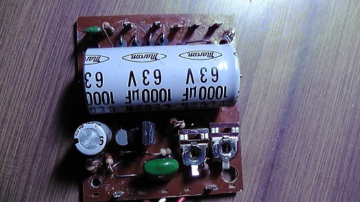
The PCB I will call speed control one ( sits on top right side of unit as one looks from behind) From my testing is at fault.
Well based on the following it is.
It's blue wire that runs from Main PCB goes to the right top terminal, I get on Multimeter from it 18volts. Yet from the terminals on left hand side of this Speed control PCB I only get 3.6volts, the red and black wires here ( + and Neg of course) supply the power to the micro switches and in turn the motor via the small PCB)
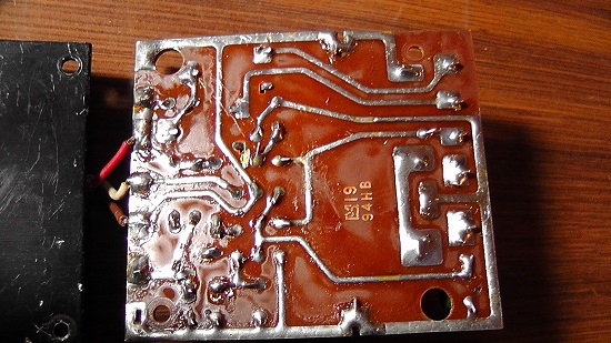
I have looked at it and I am no expert in electronics, cannot see any dry solder, well not obvious to me.
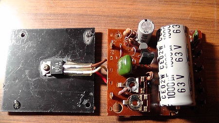
I have posted images of it both sides and also this black plastic board it screws into and has a red, white, brown smaller wires running to that black board to some electronic item I would have no idea what it is for.
Hopefully others on here may see something I cannot.
Thanks in advance
Phil
![[Smile]](smile.gif)
![[Cool]](cool.gif)
Posted by Maurice Leakey (Member # 916) on August 17, 2014, 02:58 PM:
It's notoriously difficult to spot a dry joint just by looking, a gentle prying might reveal a problem connection.
I must say I don't like the look of the joints on the end of the three wires, the soldering there looks suspicious. It would appear that the wires originally entered from the opposite side through the three holes.
Posted by Phil Mitchell (Member # 3876) on August 18, 2014, 04:14 AM:
Hi Maurice, thanks for reply.
Good observation.
Those 3 wires go to a transitor so I worked out today, Der has T on it.
Anyway what I did today was multimeter the red wire and white wire, interesting red was at first only giving me 3.6volts ( yes same reading I am getting from the power out to switches wire.)
White one gives me 10.6volts. Okay I thought why the difference.!
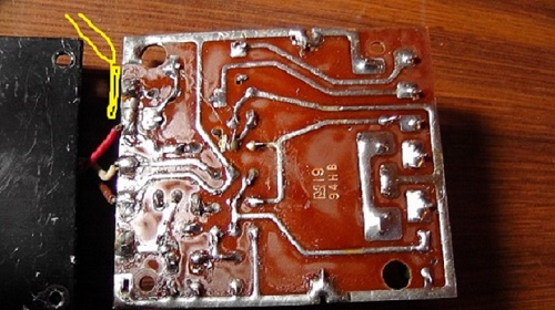
Okay I moved red wire a bit to see if it was loose, seemed a little loose, did another MM tests and now I get 4.1volts. Okay something wrong here, put MM red prod to back of circuit board near the wire and behind where the output terminal is, same readings, but it started to vary a little by a few 0.1 or 0.2 volts.
I know it is hard to see from photo, 8mm forum restricts image size, but could I be right in that some solder is missing, have a look a picture again where I have highlighted it with Paint program marking in yellow.
Maurice, I think those wires are on right way as far as those holes, to me they look like holes for other terminals blades.
Thanks again
Phil
Posted by Pete Richards (Member # 2203) on August 18, 2014, 07:32 AM:
If you like, just post me the board and I can repair it for you, I will share the results with the forum.
Alternately, I can send you a replacement board and you can put it in and see if it fixes your problem.
Posted by Phil Mitchell (Member # 3876) on August 18, 2014, 11:50 PM:
Thanks Pete,
Sent you a private message.
Cheers
Phil
Visit www.film-tech.com for free equipment manual downloads. Copyright 2003-2019 Film-Tech Cinema Systems LLC

UBB.classicTM
6.3.1.2