This is topic UPDATE: Elmo HiVision SC18 PCB problem in forum 8mm Forum at 8mm Forum.
To visit this topic, use this URL:
https://8mmforum.film-tech.com/cgi-bin/ubb/ultimatebb.cgi?ubb=get_topic;f=1;t=010659
Posted by Stuart Reid (Member # 1460) on April 26, 2016, 03:42 PM:
Making great strides with repairing my SC18, and I've safely removed the extraneous cabling. All I need to do now is replace the belts which have turned to goo, and re-attach the lamp cables, which is where I need help. They evidently attach somewhere on this PCB but i'm scratching my head as to exactly where. Can anyone either advise, or perhaps post an image of the same PCB showing the lamp connectors? Thanks!
Posted by Stuart Reid (Member # 1460) on April 27, 2016, 12:56 PM:
No-one? Please? ![[Frown]](frown.gif) I'm so close to fixing her up!
I'm so close to fixing her up!
Posted by Steve Klare (Member # 12) on April 27, 2016, 01:05 PM:
Ummmm...
This is the kind of post I normally chime in on since I'm kind of electrical, but I don't know this machine.
If it was me, I'd figure it out this way:
What's the rated voltage of the bulb you are trying to connect up?
If you look on the board, there will probably be one terminal marked with that number. This is half the battle. (That one marked "L" could be it too.)
There will be some other terminal which is the return side for this voltage. (Those two marked "0" look promising) It may be the return for several voltages. If you hook a voltmeter (AC scale) on this pair of terminals you should be able to measure the correct voltage (maybe a little higher) with the machine plugged in.
Those should be your connection points.
-I'd be wary of connecting the lamp up without the measurement: any light bulb can become a flashbulb given enough voltage!
Posted by Stuart Reid (Member # 1460) on April 27, 2016, 01:15 PM:
Thanks Steve, the 12v tap is just above the 28v so I'll measure that. Hopefully that's the answer, it just would have been nice to have double-checked with a machine that hasn't been an idiot's playground ![[Wink]](wink.gif)
Posted by Steve Klare (Member # 12) on April 27, 2016, 01:24 PM:
I'm kind of curious about the "L" and the "0" below it too.
If you also see 12VAC there maybe then measure the resistance between "L" and "12" and then the two "0"s to see if the pairs are connected.
The combination of "12" and "L" is too big a coincidence to ignore!
Posted by Bill Parsons (Member # 244) on April 27, 2016, 02:28 PM:
If you do need a photo Stuart, email me direct and I will send you one, I find uploading photos on this forum a bit of a pain!
Posted by Stuart Reid (Member # 1460) on April 27, 2016, 02:44 PM:
Thanks Bill, email sent.
Posted by Andrew Woodcock (Member # 3260) on April 27, 2016, 04:21 PM:
Glad that Bill has been able to come to your aid here Stuart.
It's not a machine I've ever seen or used or else I'd have tried to help out, just like Steve did, if I had had any experience with it.
The photo Bill sends you will undoubtedly get you to the place you're seeking here. ![[Smile]](smile.gif)
If you're listening here Bill, it is a whole lot easier elsewhere and any resolution of photograph can be posted in jpg format.
If also posted publicly,besides sending it out to Stuart here privately, it may also help others in the future here with these machines.
Just a thought here Bill.
Posted by Stuart Reid (Member # 1460) on April 27, 2016, 04:24 PM:
If Bill agrees, I'll repost what he sends me on this thread.
Posted by Andrew Woodcock (Member # 3260) on April 27, 2016, 04:26 PM:
Thank you Stuart.
Posted by Stuart Reid (Member # 1460) on April 28, 2016, 03:02 AM:
If Bill agrees, I'll repost what he sends me on this thread.
Posted by Winbert Hutahaean (Member # 58) on April 28, 2016, 05:25 AM:
The other way around is to put your own pictures after you manage fixing your projector :-)
Posted by Stuart Reid (Member # 1460) on May 10, 2016, 10:37 AM:
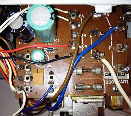
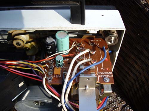
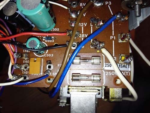
The very helpful Bill Parsons has okayed me posting these images of how the PCB ought to look:

HOWEVER, I'm still confused, and I'm sure I'm not seeing the wood for the trees. Let's look at the white cables which on Bill's images connect to L & 0. (I metered L&0 and they are a permanently connected 12v) I have one of those cables connected to 0:
However, I still have TWO tails coming off the lamp.
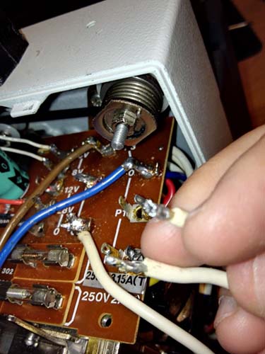
What do we think? Obviously if I connect the tails to L&0 the lamp will be permanently on.
Thanks guys
Stu
Posted by Andrew Woodcock (Member # 3260) on May 10, 2016, 11:05 AM:
One side of the circuit from the lamp should go straight to the supply, the other side from the lamp should go to through the switch contacts from the main control knob.
Then the other side of the switch contacts, back to the supply point at the PCB once again, usually via a fuse on one side or another.
[ May 10, 2016, 01:58 PM: Message edited by: Andrew Woodcock ]
Posted by Stuart Reid (Member # 1460) on May 10, 2016, 11:37 AM:
I'm going to have to dismantle to get to the bloody switch contacts aren't I?
Posted by Steve Klare (Member # 12) on May 10, 2016, 11:50 AM:
I would think there is wiring running to them already: I doubt whoever did this mod was dedicated enough to dig down and disconnect at the switch.
Posted by Stuart Reid (Member # 1460) on May 10, 2016, 12:07 PM:
But Steve, there's still an extra wire there...
Posted by Steve Klare (Member # 12) on May 10, 2016, 12:12 PM:
The trouble for me is a common reference: I don't have this machine.
Let's hope it has common assemblies with the ST-800: I have one cracked open right now (looking for parts donation!) and I'll look at it later on tonight.
Otherwise, as Andrew says: it should be a pretty simple circuit: one supply terminal on the board to the lamp, then to the switch: then back to the other terminal on the board.
-just one loop of three elements.
Posted by Andrew Woodcock (Member # 3260) on May 10, 2016, 01:45 PM:
Stuart, use your multimeter to do a continuity check on each of the cable ends you have there at the PCB.
This should then make the task of identifying the origin and relocating each cable end onto its correct terminal position really easy for you.
If your multimeter has a "bleep" function, this should make it even quicker.
Posted by Steve Klare (Member # 12) on May 10, 2016, 01:49 PM:
A "bleep" function?
Oh! That kicks in if you burn yourself with the soldering iron and you try to say "F(BLEEP)!!!!"
Some of the places I've worked we could have used that!
Posted by Andrew Woodcock (Member # 3260) on May 10, 2016, 01:56 PM:
![[Big Grin]](biggrin.gif)
Posted by Steve Klare (Member # 12) on May 10, 2016, 01:59 PM:
-I've worked with people that would have drained the battery between coffee break and lunch!
Visit www.film-tech.com for free equipment manual downloads. Copyright 2003-2019 Film-Tech Cinema Systems LLC

UBB.classicTM
6.3.1.2