This is topic Bell & Howell 10ms Wiring Problem in forum 8mm Forum at 8mm Forum.
To visit this topic, use this URL:
https://8mmforum.film-tech.com/cgi-bin/ubb/ultimatebb.cgi?ubb=get_topic;f=1;t=010768
Posted by Jeremy Burgan (Member # 5433) on June 13, 2016, 01:40 PM:
Hi!
I am brand new to the forum; I've been tasked with converting my family's old films to digital and am learning that it's a lot easier said than done! But I am really enjoying figuring out a solution that allows me to explore 8mm for myself when I'm done with this task. I bought a B&H 10ms for $10 that seemed to be working, but upon closer inspection I think it has been tinkered with and I was wondering if anyone that has one might be able to tell me if it the main function switch is wired incorrectly (and what it should be).
It mostly behaves like it's backwards (forward position goes in reverse, threading goes in reverse, reverse is forwards, rewind is really really fast forwards with the lamp extra bright? Slow motion is really fast backwards)
Thanks in advance for any guidance and the wealth of knowledge on this forum!
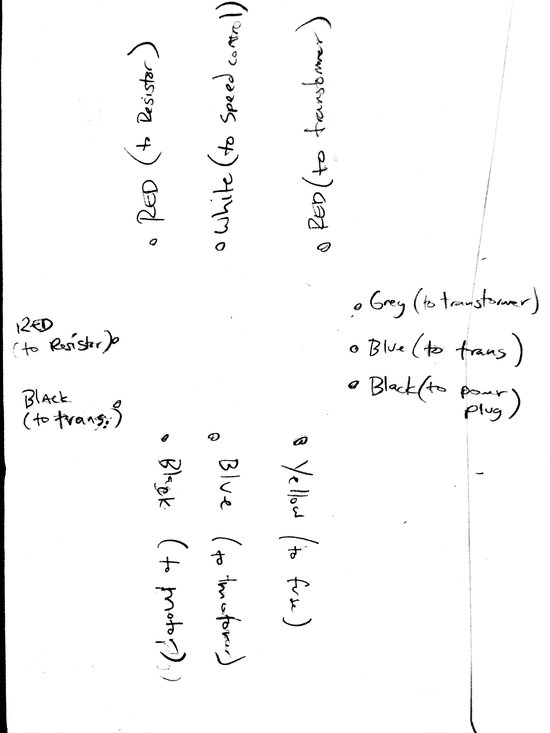
Currently It's wired (From Rear view top left around clockwise):
Red (to resistor)
White (to speed control)
Red (to transformer)
Grey (to Transformer)
Blue (to Transformer)
Black (to power plug)
Yellow (to fuse)
Red (to motor)
Black (to motor)
Black (to transformer)
Red (to lamp)
Thanks!
Posted by Jeremy Burgan (Member # 5433) on June 14, 2016, 06:13 PM:
Here is a crude diagram of the wiring from the back:
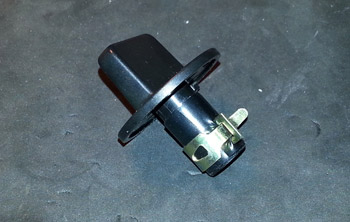
And a pic that shows some of the connections:

Posted by Janice Glesser (Member # 2758) on June 14, 2016, 09:13 PM:
Hi Jeremy...sorry it has taken a bit for me to get to your post. I've been tied up with some of my own issues. However, I finally pulled my 10MS parts machine off the shelf and took some pics. Electrical is not my forte' but maybe these pics will get you started in comparing the wiring and also help those more qualified to chime in.
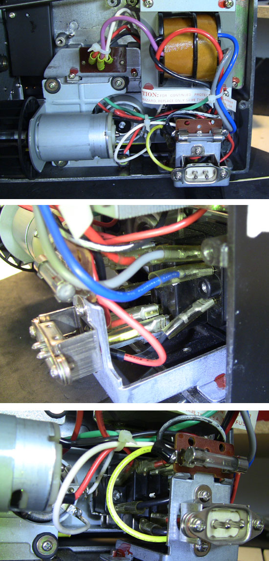
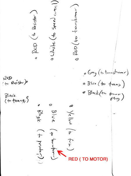
It might be difficult to see in the pics...but the only difference I see is in the 2nd photo...lower set of wires...the middle wire on mine is RED not Blue...and it goes to the MOTOR not the transformer.
Posted by Janice Glesser (Member # 2758) on June 15, 2016, 12:27 PM:
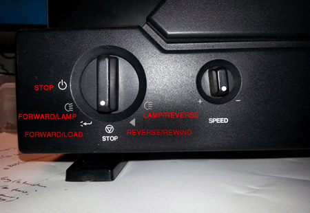
Jeremy I just noticed in your intitial post you do have the "Red to Motor" listed. If this is accurate then it appears in comparison to mine it is wired correctly. This leaves me to ask a basic question. Since the main control switch only uses symbols it's easy to get forward and reverse confused. So just verify that the behavior is opposite of what the controls show in this picture. Also... the variable speed control works with all settings forward and reverse. This needs to be adjusted.
Posted by Jeremy Burgan (Member # 5433) on June 15, 2016, 12:44 PM:
Thanks Janice, you are right! Unfortunately upon closer inspection I realized my diagram was wrong, my eyes fooled me and mine does seem to be wired correctly. And, now the motor is only turning in reverse (and only on the reverse with lamp position). So much for an easy fix... It's a shame, the unit appears to be in good shape, but apparently whatever is malfunctioning has 'kicked it up a notch'.
I suspect the fault is in the switch, since there is so little else back there, but at this point I think unless someone weighs In I have acquired a parts machine ;-)
Thanks again for pulling yours out to grab those pics. You are an amazing resource here to this forum!
Posted by Janice Glesser (Member # 2758) on June 15, 2016, 02:05 PM:
Is there any sound at all that power is going to the motor in Forward?...any humm? You might want to check with a voltmeter if there is any power going to the motor in the forward position.
It's possible that just the switch connections aren't making good contact. sometimes just turning them back and forth will remove any corrosion....or if Steve Klare is reading this... Perhaps a spray contact cleaner might help? Any other suggestion that he can test?
Posted by Steve Klare (Member # 12) on June 15, 2016, 02:37 PM:
Hi Janice and Jeremy,
I'm guessing this is a wiring issue.
Since this is a continuously variable projector I think it's DC motored: an AC motored machine would require some really sophisticated electronics to vary the motor speed, not a rheostat like this one has.
Since you can run in reverse, your drive voltage is there: maybe it's just not getting to the switch positions where the motor is supposed to be going forward.
-Could be some jumper between the reverse side of the switch and the forward side. (As always we don't have a wiring diagram so we are flying blind!)
Janice is right, what you need to do is measure the motor voltage when the thing is supposed to be going forward. You should be able to get a meter on the motor connections at the back of the control switch. With any luck you can slip the meter probes inside the sleeving and touch the Faston connection.
If you have no volts: you have an electrical problem, if you have volts with no RPMs: you have some weird mechanical issue.
I could see it being more a switch contact issue if it was one switch position, but all of the forward ones and none of the reverse?
Posted by Jeremy Burgan (Member # 5433) on June 16, 2016, 09:38 PM:
Update!
After confirming the motor was working I continued to ponder the switch being the fault, and finally decided to remove it and take it apart. Once I got it apart the internal plastic 'wafers' that fit on the shaft and determine the various electrical connections fell out in pieces. Of the 3, 2 had split apart. I guess that's why it briefly worked backwards as the pieces rotated into the opposite positions before just not moving at all. I superglued them back together and then had to try all the possible combinations by trial and error until I found the one that resulted in the correct functions.
Time consuming, but, for the time being I have a working machine (until the bulb goes, or the belt, or some other plastic part breaks lol...)
That being said, it seems like a good little machine for what it is.
Thanks again for your help! I still might try and score a better projector, and I am very curious about some of the DIY LED bulb hacks, but next I need to get a simple realtime conversion setup going so I can capture the 50 or so 50ft reels...
Posted by Steve Klare (Member # 12) on June 17, 2016, 09:56 AM:
That's a new one!
I'm glad you found it: I have the feeling replacing the switch with new would have been a no-go.
Fortunately the lamp you have is not hard to find, but it isn't cheap either. My son's projector uses this one and the lamps I use cost 1/4 as much for twice the rated hours. (His projector was free: who am I to complain?)
Someone who posts here has a replacement kit to convert CXR/CXL machines over to LED:
LED Conversion
-you just have to figure out how the economics work out for you.
Posted by Janice Glesser (Member # 2758) on June 17, 2016, 07:39 PM:
A cracked shaft on the selector knob on this model is a common fault. To repair the one on mine I wrapped it with electrical tape and then used one of these hose clamps to secure it.
Visit www.film-tech.com for free equipment manual downloads. Copyright 2003-2019 Film-Tech Cinema Systems LLC

UBB.classicTM
6.3.1.2