|
Author
|
Topic: Sankyo sound 600 motor problems repair
|
|
|
|
|
|
|
Charles Juedemann
Junior
Posts: 2
From: Union, MO, USA
Registered: Sep 2016
|
 posted September 22, 2016 03:09 PM


Hi Janice,
I am sorry I did not see your questions earlier. Here is what I know:
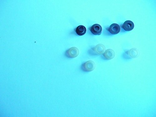
The pots are easy to find. Here are some on ebay
http://www.ebay.com/itm/DZ920-20K-OHM-Trimpot-Trimmer-Potentiometer-Pot-Variable-Resistor-RM065-203-x10-/371729341830?hash=item568ccb9d86:g:waUAAOSwFdtXzikQ
I replaced the pot nearest the edge of the circuit board, or the one near
the bottom of your photo I thnk the other one is 50k, they are marked.
Note that only two connections for the pot are needed. One is not connected,
so you will connect one side of the pot and the center. It does not matter
which one, just set the pot in the middle of the range.
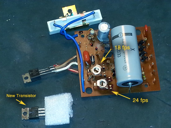
The transistor can be just about any npn si with TO3 case. The TO3 case is
like the one on the plate, that it, with a hole to mount it The leads should
be just as they are on the original, juxt don't mix them up. You can find
the transistor here
http://www.ebay.com/itm/NTE-NTE152-NPN-SI-Audio-Power-amp-Sw-/361422545804?hash=item542676638c:g:xjQAAOSwhcJWOSNQ
or go to Mouser electronics
http://www.mouser.com/?gclid=CK6Ho5XZo88CFYGFaQodbA8FrQ
Also, check that large capacitor. Put an ohmeter across the leads and if they show a short, it is probably bad.
Do not be discouraged. The smoke may very well be the transistor if the pot
is failing but I don't know. One thing about smoke, you can usually see what
part fried.
I would replace the pot and transistor. If the pot you get does not match
the holes correctly that is ok, just clip one side off. Remember, you only
use the side and center connection, or two connections.
Other than that I don't know. Look at your board with a magnifying glass to
see if you can spot any burnt areas or components. In my 600 the pot was the
failing component and I assume most motor failures are the pot which blows
the transistor.
I am sorry you are having trouble. This circuit board design is weak and I
think that board is most of the problems with this projector.
Let me know if there is anything I can do,
Charles
| IP: Logged
|
|
|
|
Phil Murat
Jedi Master Film Handler
Posts: 671
From: Villeneuve St Georges, France
Registered: Dec 2015
|
posted September 23, 2016 03:08 AM
Hello Janice,
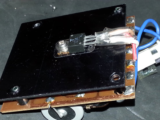
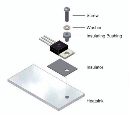
I don't know if this can help you but the TR in subject looks like a "TO220 package" so that TR lug has to be electricaly insulated from projector casing (using Mica shim plus bushing), otherwise it fails immediately and the motor runs full speed....
Once the failure fixed up, you can monitor the TR T° (not excedind 60°C)
An other common failure is an Electrolitic capacitors (or may be an other like polyester capacitor) which had dried out and makes a short circuit. Considering age of the projector, and cheapness of this components, very easy to find too, don't try to test it and renew directly.....
If capacitor original voltage is not available, choose upper rate, just the Capacitor size increase. (never go below original values)
Also, You can check the Diode next to TR or Rectfying Bridge if installed somewhere....
Hope that helps.....
[ September 23, 2016, 05:04 AM: Message edited by: Phil Murat ]
| IP: Logged
|
|
|
|
Phil Murat
Jedi Master Film Handler
Posts: 671
From: Villeneuve St Georges, France
Registered: Dec 2015
|
posted September 24, 2016 03:49 AM
Hello Janice,
I can see the "Mica" Shim on the picture. This is good.
Also , insure you a Nylon bushing is installed between screw head and TR Lug .
Typical TR bushings :
Pay attention to the screw lengh (TR securing), if too long it could interfer with board cooper tracks.....
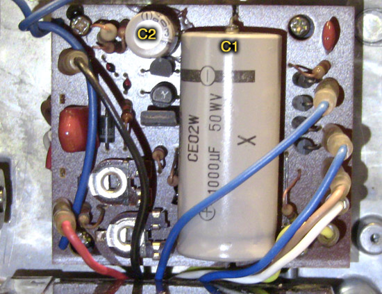
An other thing, I can see a "grey Spot" on the big Capacitor (1000 µF) on the 1st picture , is it dust or something else ?
/////// INFO : TR DATA SHEET:
2SD234
Some measures :
It could be interesting to know these DC voltages (When setted on 24fps) :
1) U at motor connectors
2) U at TR "in"
3) U max design of the motor (Check on Motor Label)
4) U and I between Pins 1 & 3
Pin 1 is the "Control" (Base) of the TR. Higher is the current going to Pin 1 , more current is available for the Motor. If Power TR is OK, TR "Control" (of the Pin 1 current) is probably faulty and if speed adjustable resistors (18fps & 24Fps) have no effect , check (or replace as a set) T1 & T2 (small TR) and associated Capacitor(s).
I assume , if disconnecting Power TR Pin 1 = Motor Not powered, so , also means "Power TR" is ok (Not Shorted)........To be confirm
Let us know
Phil
[ September 24, 2016, 02:30 PM: Message edited by: Phil Murat ]
| IP: Logged
|
|
|
|
|
|
|
|
Phil Murat
Jedi Master Film Handler
Posts: 671
From: Villeneuve St Georges, France
Registered: Dec 2015
|
posted September 27, 2016 06:58 AM
Hello Janice,
I am just a beginner too , for Electronic , and I am also learning a lot along the met tips ......
Considering the failure , here are the conditions that I understood :
- Motor runs Full speed
- Runs full speed either 18 or 24 fps set
- Action on Adjustable Resistors Has no effect.
To simplify , I was calling :
- U as Voltage and I for Amps.
- TR is NPN (TO220 package) power transistor
- T1 & T2 are small TR's devoted to command TR (TR Pin 1).
On picture, T2 is pointed out , I can see an other one , next to T2 (small "Half moon" shape) that I call T1.
T1 & T2 are working together as a "cascade" installation.
Here is an idea to carry on Trouble shooting :
In summary, PCB shows 2 "stages" : Power & Command
A) To be sure 2SD234 (power) is OK, I assume disconecting Pin 1 will make the motor not running : If this state is observed, I assume 2SD234 is not shorted between Pins 2 & 3.
B) If A) satisfactory, probably means Command is faulty.
Also , according to 2SD234 Datas, U measured from Pin 1 to 3 do not exceed 5 V.
If T1 or T2 are faulty (shorted), too much Amps(Command Amps is very low normaly, may be 0,1 A) go to Pin 1 making TR opened "Full Power" available for motor.
T1 & T2 are certainly very common & cheap components (May be you can get 10 of each for 1$....)
Transistors Don't like 2 things : short circuited and High T°.
So before to replace a faulty one it is important to find "root" failure.
Old Electolitic Capacitors are often time the issue.
On the picture , I can see a small Radial Electrolitic Capacitor (Light Blue Cylinder), it is next to T1 & T2. If it is confirmed to be directly linked to T1 & T2, it could be profitable to replace it if T1 & T2 are replaced.
"NEW" ELECTROLITICS RADIAL CAPACITORS configuration (Choose a standard 85°C class) :
- The "ground" (-) , is next to the Strip along the cylinder and associated wire is Short size.
- (+) is the longer wire.
Manage a mark before removing and do not reverse installation......
Hope that helps you
Let us know
Phil
[ September 29, 2016, 04:58 AM: Message edited by: Phil Murat ]
| IP: Logged
|
|
|
|
|
|
|
|
|
|
Phil Murat
Jedi Master Film Handler
Posts: 671
From: Villeneuve St Georges, France
Registered: Dec 2015
|
posted September 30, 2016 06:55 AM
Hello Janice,
Here is what I understand from your test :
When installed , measured voltage between "Base" to "Emetter" is around 0,6v , in that case this is OK.
I can't confirm but, I am not surprised by "0"V measured from "Base" to "Collector" , I assume this is a normal condition :
When operating , considering NPN , "Command" current go from "Base" to "Emitter" (Reverse flow for PNP Transistors).
Once board installed , experiment disconnecting "TR Power" pin 1 only (2 & 3 stay connected). If motor don't run (instead of running "full power" 2 & 3 connected) means TR condition is satisfactory (Not shorted).
So, means also that too much current is going to PIN 1, means also to investigate around TR1 & TR2 & Capacitor(s) Team.....
You are approaching to the key ![[Wink]](wink.gif)
NB
In an other way, imagine a small modulated signal enters PIN 1 of any TR , you can collect same signal on Pin 3, however, with much more power.......... In that case TR works as an Amplifier for sound
| IP: Logged
|
|
|
|
Phil Murat
Jedi Master Film Handler
Posts: 671
From: Villeneuve St Georges, France
Registered: Dec 2015
|
posted October 02, 2016 01:01 AM
Hello Janice,
A) There is a high probability original TR Power is in good condition.
The breakdown design T° is around 150 °C , if you feel casing "extremly" hot, means T° is around 70°C. This is a bit too much and needs to be pull down.
B) I am not surprised considering T1 condition. If you find a capacitor fitted next to TR1 , it could be profitable to replace it (a faulty capacitor could be the "hiden" issue)
C) 5v or 6V are just the "breakdown" limit for these Power TR Base.
Normal operating voltage when regulating is around 0,6v for our case.
The Max Voltage limit is around 50V : You can measure Voltage "going in" from Big Capacitor Pins (1000 µf / 50V).
NTE152 looks a bit stronger, However , once installed, the 18/24 Adustable Resistors could need to be trim again.
IMPORTANT:
Some "vintage" TR are difficult to find and can be replaced by an "Equivalent" item. if overall limits are the same, however "response" curves could be different.
I have experienced this situation as I faced a similar failure for a BEAULIEU : I had to reinstall the same TR reference because régulation wasn't responding correctly.....
For exemple : If installing NTE152 makes the motor running to High (for any 18/24 setting) , you could be induced to compensate by adding a small resistor (may be 10 K) just before PIN 1.
As a primary experience, if original TR works properly, I suggest to keep it.
Let us know
[ October 02, 2016, 04:33 AM: Message edited by: Phil Murat ]
| IP: Logged
|
|
|
|
Phil Murat
Jedi Master Film Handler
Posts: 671
From: Villeneuve St Georges, France
Registered: Dec 2015
|
posted October 03, 2016 02:08 AM
Hi Janice,
Due to this new picture I can see an other "small" TR (TR3, "half moon" shape) very next to C2 too. It probably works with T1 and T2, so, normally the thinking is identical for this TR.
C2: If 6,3 V is not available , you can choose 10 , 16, or 25v as well, it doesn't matter. (You just need "room" enough to fit it properly)
"New Generation" Capacitors are smaller than old ones for same value, so you can upgrade to a higher Voltage Limit at your conveniance.
POTs : Probability both pots to fail together and in a same time is very low.....
[ October 03, 2016, 04:20 AM: Message edited by: Phil Murat ]
| IP: Logged
|
|
|
|
|
|
|
|
|
|
|


 UBBFriend: Email this page to someone!

![[Frown]](frown.gif)
![[Smile]](smile.gif) Does "U" stand for VOLTAGE? Does "I" stand for CURRENT (Amps)? In regards to your reference to "T1 & T2 (small TR)"...Are you saying to replace the "T1" large NPN Power Transistor on the heat sink and the "T2" smaller TR on the top of the PCB?
Does "U" stand for VOLTAGE? Does "I" stand for CURRENT (Amps)? In regards to your reference to "T1 & T2 (small TR)"...Are you saying to replace the "T1" large NPN Power Transistor on the heat sink and the "T2" smaller TR on the top of the PCB?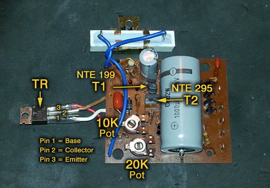


 Printer-friendly view of this topic