8mm Forum


my profile | my password | search | faq | register | forum home
  next oldest topic   next newest topic
» 8mm Forum   » 8mm Forum   » Porst 100 Sound- not rewinding (Page 1)

 - UBBFriend: Email this page to someone!  
This topic comprises 2 pages: 1  2 
 
Author Topic: Porst 100 Sound- not rewinding
Urmas Jaagusoo
Junior
Posts: 20
From: Tartu, Tartumaa, Estonia
Registered: Jan 2015


 - posted September 16, 2015 10:18 AM      Profile for Urmas Jaagusoo   Email Urmas Jaagusoo   Send New Private Message       Edit/Delete Post 
Hello! I have trouble with my Super 8mm projector Porst 100 Sound. I bought it last year, it worked great. Lately the rewinding speed seemed a bit too slow. Yesterday I watched a film, rewinding was ok. After the second movie the rewinding stopped. Turning the knob does not do anything. Forward speed ok. Light goes on in both directions. What could be the problem? Is the DC motor dying? Has anyone a clue if there is a market for new/used motors (DC Motor FUJI Micro FM-43-H)?

Gratefully Urmas from Estonia.

 |  IP: Logged

Steve Klare
Film Guy

Posts: 7016
From: Long Island, NY, USA
Registered: Jun 2003


 - posted September 16, 2015 10:32 AM      Profile for Steve Klare   Email Steve Klare   Send New Private Message       Edit/Delete Post 
Welcome Urmas,

Usually if a motor dies in one direction, it will be dead in both. So your motor is probably OK.

I don't know your machine, but from others I do know there are usually two switches which switch both your motor wires to either (+) or (-) DC to choose the direction of shaft rotation.

I'm thinking one of your switches has a worn contact, probably even burned and oxidized.

If you measure the motor voltage you will probably see "+/-" in forward and something like +/+ or -/- in rewind (referenced to chassis).

--------------------
All I ask is a wide screen and a projector to light her by...

 |  IP: Logged

Urmas Jaagusoo
Junior
Posts: 20
From: Tartu, Tartumaa, Estonia
Registered: Jan 2015


 - posted September 16, 2015 10:55 AM      Profile for Urmas Jaagusoo   Email Urmas Jaagusoo   Send New Private Message       Edit/Delete Post 
Thank You, Steve for a quick answer. I haven't checked the switch yet, but I will now!

 |  IP: Logged

Maurice Leakey
Film God

Posts: 5895
From: Bristol. United Kingdom
Registered: Oct 2007


 - posted September 16, 2015 11:31 AM      Profile for Maurice Leakey   Email Maurice Leakey   Send New Private Message       Edit/Delete Post 
http://www.super8data.com/database/projectors_list/projectors_porst/porst_sound_100.htm
Looks a very interesting projector which is made by Elmo.

--------------------
Maurice

 |  IP: Logged

Steve Klare
Film Guy

Posts: 7016
From: Long Island, NY, USA
Registered: Jun 2003


 - posted September 16, 2015 11:38 AM      Profile for Steve Klare   Email Steve Klare   Send New Private Message       Edit/Delete Post 
Good!

Then just maybe I DO know something about it!

It's not exactly an Elmo in the same way a Bolex SP-80 is a Eumig. The control knob is up by the lens instead of back over the rear feet. The volume knob is much higher up on the chassis too. It has a carry strap (like a Eumig 800) instead of the hard Elmo handle.

It looks like it's got green plastic guides, but it doesn't seem to be an Elmo ST dressed in a different outer case.

--------------------
All I ask is a wide screen and a projector to light her by...

 |  IP: Logged

Urmas Jaagusoo
Junior
Posts: 20
From: Tartu, Tartumaa, Estonia
Registered: Jan 2015


 - posted September 16, 2015 12:30 PM      Profile for Urmas Jaagusoo   Email Urmas Jaagusoo   Send New Private Message       Edit/Delete Post 
I opened the projector and there are three same looking black rectangular switches at the right side of the control knob. The front one swithes the motor on to wind forward, the middle one is for rewind and the last one is for the light. Seems quite an ordeal to get through to take the switches out.As I have no knowledge of electrical equipment I have to leave it to the professionals. I will try to find someone, although I have no high hopes (Super 8mm fever hasn't reached Estonia and very few people still have projetors, even less no how to fix problems).I guess in the end I have to sell it to someone for spare parts (or to fix it). Luckily I have one more working projector.

 |  IP: Logged

Steve Klare
Film Guy

Posts: 7016
From: Long Island, NY, USA
Registered: Jun 2003


 - posted September 16, 2015 01:10 PM      Profile for Steve Klare   Email Steve Klare   Send New Private Message       Edit/Delete Post 
This sounds very Elmo-ish!

Probably the two motor switches are each for one terminal of the motor. Each one chooses either (+) or (-) and they are set up to choose whichever one the other one doesn't.

The good news is if the switches are the same Elmo used, they are still available brand new and shouldn't be hard to find.

The bad news is you are correct: changing them can be pretty terrible. What you have is a steel plate that aligns this stack of switches with an insulator between each switch and one on each end of the stack (4 insulators, 3 switches and a bunch of spacers for the third screw.) aligning all this stuff on the control knob are three machine screws maybe 10 cm long that pass through the plate, the insulators, the switches and then into the chassis.

I replaced a switch once. After I soldered the new one in I tried to stack all this stuff up and hold it in place while I put the screws in.

-WRONG!

The pieces kept twisting and turning and I couldn't get the screws all the way through the holes because they refused to align.

After I fought this for way too long I grabbed the plate, put in the screws and started stacking insulators, switches and spacers on the screws. When the stack was complete I carefully turned it over and installed the whole thing on the chassis.

PS: If I knew what a mess this would turned into I would have replaced ALL the switches.

-but that will be a fight for another day. (I'm sure.)

--------------------
All I ask is a wide screen and a projector to light her by...

 |  IP: Logged

Urmas Jaagusoo
Junior
Posts: 20
From: Tartu, Tartumaa, Estonia
Registered: Jan 2015


 - posted August 09, 2016 07:48 AM      Profile for Urmas Jaagusoo   Email Urmas Jaagusoo   Send New Private Message       Edit/Delete Post 
Hi! I have been looking now for quite a while at my poor projector in a box under the kitchen chair and I thought I'd try to fix it. If I somehow got the switch out and posted a picture here, could somebody help me find out what kind of a switch it is and help me find a new one to replace the not working one?

 |  IP: Logged

Andrew Woodcock
Film God

Posts: 7477
From: Manchester Uk
Registered: Aug 2012


 - posted August 09, 2016 07:58 AM      Profile for Andrew Woodcock         Edit/Delete Post 
Give it a go Urmas!

I am sure there are plenty of people here who can come up with a similar suitable replacement.

Try to photograph the actual switch though if at all possible, not just its control knob on the front of the projectors fascia panel. [Wink]

The more detail you can give of it, the greater the chance of someone being able to match you up with a suitable replacement.

Look for any diagrams or writing on the switch. This really helps! [Wink]

--------------------
"C'mon Baggy..Get with the beat"

 |  IP: Logged

Barry Fritz
Phenomenal Film Handler

Posts: 1061
From: Burnsville, MN, USA
Registered: Dec 2009


 - posted August 09, 2016 10:44 AM      Profile for Barry Fritz   Email Barry Fritz   Send New Private Message       Edit/Delete Post 
Before you start messing with the switches, remove the back cover and observe the gears at the take-up and feed arms. Run the projector in forward while watching both sets of gears, and then run it in rewind while watching the gears. Are the gears turning in both positions? You may simply have a belt issue or a clutch issue in one of the gears.

 |  IP: Logged

Urmas Jaagusoo
Junior
Posts: 20
From: Tartu, Tartumaa, Estonia
Registered: Jan 2015


 - posted August 09, 2016 03:35 PM      Profile for Urmas Jaagusoo   Email Urmas Jaagusoo   Send New Private Message       Edit/Delete Post 
Thanks Andrew and Barry! I will try to post a photo of the switch.But it seems a bit complicated (not for me, but for the computer). Keeps telling me that my log in failed.Though I am logged in. Hm.. I will find out what the problem is and hopefully someone here can tell me where from I could get a new switch after I manage to post a photo of it.

 |  IP: Logged

Urmas Jaagusoo
Junior
Posts: 20
From: Tartu, Tartumaa, Estonia
Registered: Jan 2015


 - posted August 10, 2016 03:40 AM      Profile for Urmas Jaagusoo   Email Urmas Jaagusoo   Send New Private Message       Edit/Delete Post 
Here is the switch:

 -

 |  IP: Logged

Andrew Woodcock
Film God

Posts: 7477
From: Manchester Uk
Registered: Aug 2012


 - posted August 10, 2016 03:54 AM      Profile for Andrew Woodcock         Edit/Delete Post 
If you photograph it again Urmas, so we can read the writing on the body, I have no doubt there is a good chance we would be able to find you an exact replacement.

Either way, no problems as it is just a standard micro switch by the looks of things and they are very easily found.
You just need to ensure it at least matches the original rating.
It doesn't matter if it exceeds the original rating if this is all that can be found easily.

Have you tested it with a multimeter to see if this one works or not?

--------------------
"C'mon Baggy..Get with the beat"

 |  IP: Logged

Urmas Jaagusoo
Junior
Posts: 20
From: Tartu, Tartumaa, Estonia
Registered: Jan 2015


 - posted August 10, 2016 07:11 AM      Profile for Urmas Jaagusoo   Email Urmas Jaagusoo   Send New Private Message       Edit/Delete Post 
My skills end where it comes to a multimeter and other technical equipment. So the answer is no, I haven't tested it.I have a multimeter though somewhere, may be it is time I taught myself how to use it. The writing on the switch appears to be really small on the photo: There is a triangle on the upper right where is "04" in. Then there is: AM47008 007 29 T
3A125V~2A250V~ . There is something on the other side as well, but I have to wait till I get home to make new photos.

 |  IP: Logged

Andrew Woodcock
Film God

Posts: 7477
From: Manchester Uk
Registered: Aug 2012


 - posted August 10, 2016 07:29 AM      Profile for Andrew Woodcock         Edit/Delete Post 
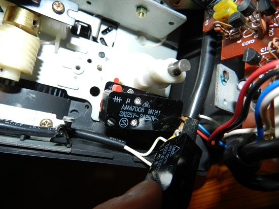
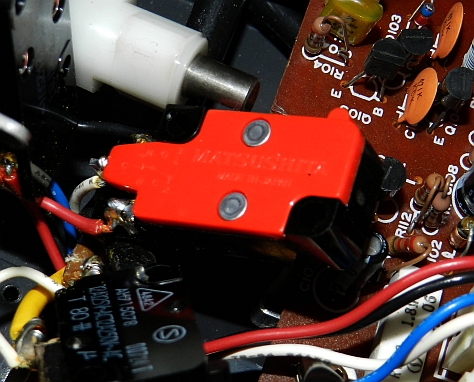
it appears from your photograph then Urmas,that you have three identical microswitches in a row being activated by cam lobes from your mechanical rotary knob position (not in picture, so I am surmising here).

I just want you to be certain it is a faulty switch that is at fault and even then, that it is definitely the switch you have your thumb on in the photo.

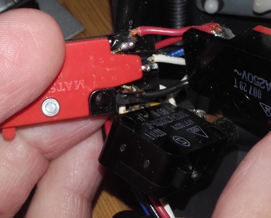
The microswitches appear to bolt onto the steel bracket at top and bottom in a bank together. (Only you know this for certain as it is you who has dismantled it to get to this stage).

You need to establish when bolted firmly in the correct position, whether each switch is first, making a tiny clicking sound as the contacts are closed by the cam lobes, one at a time, for each switch position.
Then secondly, if all is ok with the above, whether or not the actual circuit from the switch is being closed as should be the case to enable current to flow correctly through each of the 3 circuits.

For this you really need to be able to test each switch.

Sometimes, it may not be the actual switch, more a case of poor contact from the cam to the switch button or lever.

All of this needs to be established before you can make a further decision really, otherwise you may just be wasting your money at this stage.

--------------------
"C'mon Baggy..Get with the beat"

 |  IP: Logged

Urmas Jaagusoo
Junior
Posts: 20
From: Tartu, Tartumaa, Estonia
Registered: Jan 2015


 - posted August 10, 2016 07:49 AM      Profile for Urmas Jaagusoo   Email Urmas Jaagusoo   Send New Private Message       Edit/Delete Post 
Actually I suspect that the fawlty one is the one which is in the middle i.e. not under my thumb but right in the middle of the photo. When I turned the knob and looked at the switches, then the front one worked ok and that one makes the film wind forward. But when I turned the knob to the rewind position, then the little metal part moved against the switch but the motor did not start. I assumed the problem must be the switch. I also tried to push the switch with a srewdriver to be sure, that the little metal part is not somehow too far (so it doesn't reach the switch). But that did not change anything. But it is good advice to be absolutely sure, and the only way I suppose is to use a multimeter, as you suggested. That will be a tough job for me though because I have never used one and to be honest I am not quite aware of the basics how the multimeter works.But I cannot give up [Smile] thanks! My next job is finding out whether the switch I suspect does not do its job, works or not.If someone could give me a hint how can I run the test with a multimeter, it would be great! I load some more photos when I reach home.

 |  IP: Logged

Andrew Woodcock
Film God

Posts: 7477
From: Manchester Uk
Registered: Aug 2012


 - posted August 10, 2016 07:55 AM      Profile for Andrew Woodcock         Edit/Delete Post 
You do not need power to the unit to test whether or not these switches are working correctly.

Make sure the projector is fully disconnected from the mains supply Urmas before you begin anything!

--------------------
"C'mon Baggy..Get with the beat"

 |  IP: Logged

Urmas Jaagusoo
Junior
Posts: 20
From: Tartu, Tartumaa, Estonia
Registered: Jan 2015


 - posted August 10, 2016 07:58 AM      Profile for Urmas Jaagusoo   Email Urmas Jaagusoo   Send New Private Message       Edit/Delete Post 
Will do! Thanks! Safety first.

 |  IP: Logged

Andrew Woodcock
Film God

Posts: 7477
From: Manchester Uk
Registered: Aug 2012


 - posted August 10, 2016 08:03 AM      Profile for Andrew Woodcock         Edit/Delete Post 
Indeed! [Wink]

--------------------
"C'mon Baggy..Get with the beat"

 |  IP: Logged

Steve Klare
Film Guy

Posts: 7016
From: Long Island, NY, USA
Registered: Jun 2003


 - posted August 10, 2016 08:42 AM      Profile for Steve Klare   Email Steve Klare   Send New Private Message       Edit/Delete Post 
Yes, this is a job for the Ohms function.

Put the meter in Ohms, touch the leads together, you should see some number close to zero: this is a closed circuit. Take the leads apart, you should see something like "OL": this is an open circuit.

This way you can test with nothing more dangerous than a 9 volt battery involved.

If there are only two terminals you should be able to put the meter across them and at least see the reading go from a small one to a large one when you click the switch. (It may only go to "OL" if you disconnect the wiring from the terminals)

If there are three terminals there should be one that connects to one of the other two at a time, but not both. This one will be labeled something like "COM".

--------------------
All I ask is a wide screen and a projector to light her by...

 |  IP: Logged

Andrew Woodcock
Film God

Posts: 7477
From: Manchester Uk
Registered: Aug 2012


 - posted August 10, 2016 08:56 AM      Profile for Andrew Woodcock         Edit/Delete Post 
[Smile] [Wink]

--------------------
"C'mon Baggy..Get with the beat"

 |  IP: Logged

Urmas Jaagusoo
Junior
Posts: 20
From: Tartu, Tartumaa, Estonia
Registered: Jan 2015


 - posted August 10, 2016 10:56 AM      Profile for Urmas Jaagusoo   Email Urmas Jaagusoo   Send New Private Message       Edit/Delete Post 
Here is one more photo of the switch, other side. Text on it reads: MATSUSHITA and Made In Japan. There is also a scheme on it.
 -

 |  IP: Logged

Steve Klare
Film Guy

Posts: 7016
From: Long Island, NY, USA
Registered: Jun 2003


 - posted August 10, 2016 11:41 AM      Profile for Steve Klare   Email Steve Klare   Send New Private Message       Edit/Delete Post 
I love a good scheme!

How many terminals have wires soldered to them?

--------------------
All I ask is a wide screen and a projector to light her by...

 |  IP: Logged

Urmas Jaagusoo
Junior
Posts: 20
From: Tartu, Tartumaa, Estonia
Registered: Jan 2015


 - posted August 10, 2016 03:01 PM      Profile for Urmas Jaagusoo   Email Urmas Jaagusoo   Send New Private Message       Edit/Delete Post 
Hi. I am glad you guys help me! All of the terminals have wires soldered to them. Here is what it looks like, and there's even a scheme visible.
 -

 |  IP: Logged

Andrew Woodcock
Film God

Posts: 7477
From: Manchester Uk
Registered: Aug 2012


 - posted August 10, 2016 03:14 PM      Profile for Andrew Woodcock         Edit/Delete Post 
The terminals as represented by the small schematic diagram are
NO = normally open
NC= normally closed
C= common

Common carries one side of the circuit for in and out of the switch.

NO is the incoming cable to the switch
NC is the outgoing cable from the switch

You should get a circuit between NC and a C when the red small button on top of the switch is depressed by doing a continuity check (zero ohms) on your multimeter if it is working correctly.

When the red micro switch button is released, the multi meter display should then show 1 (open circuit), keeping the multimeter probes still on C and NC.

Zero ohms on your multimeter = closed circuit or circuit made
1 on your multimeter = open circuit or out of range ( many thousands of ohms)

[ August 11, 2016, 03:51 AM: Message edited by: Andrew Woodcock ]

--------------------
"C'mon Baggy..Get with the beat"

 |  IP: Logged


All times are Central
This topic comprises 2 pages: 1  2 
 
   Close Topic    Move Topic    Delete Topic    next oldest topic   next newest topic
 - Printer-friendly view of this topic
Hop To:

Visit www.film-tech.com for free equipment manual downloads. Copyright 2003-2019 Film-Tech Cinema Systems LLC

Powered by Infopop Corporation
UBB.classicTM 6.3.1.2