|
Author
|
Topic: GS1200 Total Shut Down
|
Paul Adsett
Film God
Posts: 5003
From: USA
Registered: Jun 2003
|
 posted September 21, 2019 11:04 AM


Well my GS1200 Version 2, which is my main projector, has totally failed. No power, no motor or fan, just the amplifier light and front side light come on. As soon as I throw the power switch on, it blows one of the 3.5 amp fuses on the transformer panel.
No idea what caused this but I had been having problems with the rear take up not working and was trouble shooting in the area of the big Matsushita relay on the control board. I found that if I gave that relay a tap then the rear take up would rotate for several minutes before quitting. I repeated this several times and then decided to reheat all the solder points that connect that relay to the control board, thinking it may have been a cold solder joint problem. It was after doing this that the projector refused to run at all, and I found out that it was blowing one of the main fuses on the transformer board.
Help! Any sugestions appreciated.
--------------------
The best of all worlds- 8mm, super 8mm, 9.5mm, and HD Digital Projection,
Elmo GS1200 f1.0 2-blade
Eumig S938 Stereo f1.0 Ektar
Panasonic PT-AE4000U digital pj
| IP: Logged
|
|
|
|
|
|
|
|
|
|
|
|
|
|
Phil Murat
Jedi Master Film Handler
Posts: 671
From: Villeneuve St Georges, France
Registered: Dec 2015
|
 posted October 03, 2019 02:01 AM


Hi Paul,
Very High probability you found out "issue root" [Wink] :
Upon some research in forums backgrounds from my side (German Forums too) some GS1200 owners have reported this typical problem (35V fuse burnt due to failed "Governor").
Often time , when "Governor" board fails, it generates a short-circuit on 35V power supply.
I/C UPC1002C fitted on "Governor" Board is probably out of order due to poor caps around.
Also it can be an aging failure which shows up for machines which have accumulated many working hours.
UPC1002C is an I/C "NEC" component, a bit difficult to get , but still available (minimum price around 5Eur in China) .
In case "Governor" refurbishment option is choosen :
A) To remove UPC1002C, it can be more confortable to cut pins before and to desolder each pin by each one in order to limit stress of board.
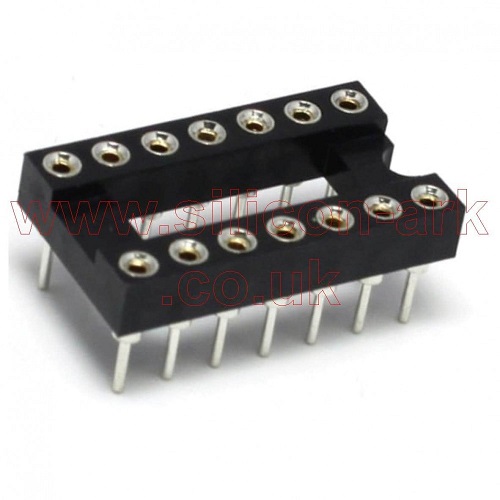
B) Install 14 pins DIL socket on board first then simply clips "firmly" new I/C on socket.(This minor modification allows fast futire installation/removal of I/C).
Pay particular attention during socket and I/C : Do not reverse position
C) Suggest to replace all caps and small transistors as an corrective action package.
Here is suggested 14 pins socket :

[ October 03, 2019, 05:54 AM: Message edited by: Phil Murat ]
| IP: Logged
|
|
|
|
|


 UBBFriend: Email this page to someone!
 Printer-friendly view of this topic


 UBBFriend: Email this page to someone!
 Printer-friendly view of this topic