Posts: 7477
From: Manchester Uk
Registered: Aug 2012
posted August 16, 2017 05:43 AM
Got it thanks Phil.
Please see my one last question above Phil.
I'm guessing 375HZ but this is purely a guess at this stage,based on your quoted figure of 500hz at 24fps and the fact that I'd expect this to be linear by association.
-------------------- "C'mon Baggy..Get with the beat"
Posts: 671
From: Villeneuve St Georges, France
Registered: Dec 2015
posted August 16, 2017 09:02 AM
Yes Andrew , your estimation is certainly correct.
I have only experimented this method with 24 Fps setting only. I assume result for 18 Fps is around 375 Hz value as an extrapolation. But this is something to confirm practicaly
So, I test more points around 18 Fps & 24 Fps for better accuracy
[ August 16, 2017, 10:11 AM: Message edited by: Phil Murat ]
Posts: 7477
From: Manchester Uk
Registered: Aug 2012
posted August 16, 2017 09:10 AM
Thanks Phil and once I have a suitable meter, I will let you know what my own readings are from the Stereo model. It's running perfectly fine so it will be nice to get some of my own reference points to collaborate with your own on these.
Bill informed me that often when there is issue on the Capstan circuit, it simply does not run in stop mode but with main power switched on of course.
From experience, Bill also advises that a special long thin purpose built instrumentation screwdriver should be fashioned for adjusting the trim pots as many of these are concealed dangerously close to the revolving shutter, which from having a look recently, I can certainly confirm is very much the case! I certainly wouldn't want my hand anywhere those trim pots when the shutter is running!😂
There is also a very useful piece recorded in a late FFTC edition that advises changing one of the transistors to a higher rated type (1.5a instead of 0.5a). This was discovered by a chap called Luigi and he advised that one in particular from the CS 140 IC, simply wasn't the correct rating for the demand placed on it and it caused two machines that he was servicing to fail. Once changed to the uprated version, both came back to life and worked perfectly.
I have the original piece if you'd like me to mail you a copy for you to read?
-------------------- "C'mon Baggy..Get with the beat"
Posts: 671
From: Villeneuve St Georges, France
Registered: Dec 2015
posted August 16, 2017 10:17 AM
Yes Andrew , You are right :
Last Beaulieu's Machines are showing an ugraded Transistor from production to drive Capstan Motor. I have already install it on my boards as this is a very common failure.
Reference is BD136 (T4 Transistor Position on SEREO Family) : Pay particular attention for terminals position which is different from former one. Also, you will need to drill out former Board terminals holes (up to 0,9mm) to install new one.
Normally, if input voltage is properly rated (around 13V), there is no reason for CS140 to fail out. Moreover "CS140" IC features a built in "Short Circuit" Protections available on Pins 9 & 16 both.
Posts: 7477
From: Manchester Uk
Registered: Aug 2012
posted August 16, 2017 10:45 AM
Thanks Phil, let's hope I never need go there! Drilling circuit boards given their delicate nature is not something I want to experience.
I'd need to have a look to see which type is fitted to my own, I've not studied the transistors on my motor board so far.
Yes I've seen the SC protection feature on the CS 140 from the Cherry Tree data sheet for this component.
-------------------- "C'mon Baggy..Get with the beat"
Posts: 671
From: Villeneuve St Georges, France
Registered: Dec 2015
posted August 16, 2017 10:57 AM
Upgrading T4 transistor is pretty easy to do. I have used a magnifying glass of course because I have not same sight as young.
Reaching RA6, RA7 or RA17, RA18 is a game of skill. To do it, I have preformed a kind of extra long screwdriver from a "more or less" flexible plactic rod...
To be note the "Cloned" Board pots (ALL pots) can be setted SAFELY in any conditions , OUTSIDE from the Machine due to an EXTENSION HARNESS using. Then, when properly adjusted , board is installed in the machine.
Posts: 7477
From: Manchester Uk
Registered: Aug 2012
posted August 16, 2017 05:51 PM
I will take a preset cloned Motor board from you Phil once you make them available. It would make a great addition to my spares for these machines. Also please advise on electronics suppliers for the mask light bulb and LDR's if you know of any. I have one of each from Beaulieu Cinetec, but another of each would not go a miss for the future.
-------------------- "C'mon Baggy..Get with the beat"
Posts: 7477
From: Manchester Uk
Registered: Aug 2012
posted August 17, 2017 05:29 PM
It certainly appears similar thanks Phil. I'd have to get my original spare out of storage to compare the physical dimensions.
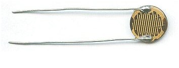
Have you any input for the Light Dependent Resistors used in these Phil? They are very very small for one of these components and nothing like others I have been used to seeing.
-------------------- "C'mon Baggy..Get with the beat"
Posts: 671
From: Villeneuve St Georges, France
Registered: Dec 2015
posted August 18, 2017 02:31 AM
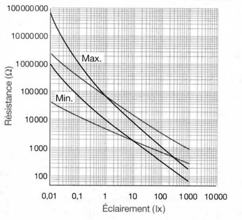
Concerning Photoresistors inside Sensor Mask , Andrew ,The only things I know :
- There are like this
- Works like this (The diagram below is just for information but do not match for the ones used in BEAULIEU's)
- 2 Photoresistors are installed inside the Mask housing
- Their overall reliability is "normaly" excellent.
In this particular case, BEAULIEU' design choice is simply "Excellent" as the Mask assembly looks "unbreakable" offering a high steady operating and reliability (no parts subject to wear).
For this reason, my machines keep RA1 (RA19) setted at mid-range to increase bulb life, also regulation response stays fully satisfactory in this condition.
From my own experience, the only things to watch out is :
- Avoid dusts to come inside Mask assembly - Insure Copper Slider is free - Main faults (Sensor Out Off response) come from bulb terminals which can cut easily
Posts: 7477
From: Manchester Uk
Registered: Aug 2012
posted August 18, 2017 04:08 AM
Thanks Phil. I haven't had any issues either so far with this assembly but as said, I ordered one of each of the lamp and LDR (Photo Cell) just as precautionary measure. The LDR they supplied looks even smaller than the one above and was from their official stock pile.
As you imply though Phil, I'm sure they potentially will last a lifetime or more in their dust sealed chamber.
-------------------- "C'mon Baggy..Get with the beat"
Posts: 7477
From: Manchester Uk
Registered: Aug 2012
posted August 18, 2017 04:25 AM
All I can tell you at present Phil, is Wittner Cinetec still have one or two originals from their existing Beaulieu stock pile but of course they are not 0.9€ and you may feel a perfectly acceptable equivalent can be sourced elsewhere for far less.
Finding a data sheet now for the originals may prove very tricky indeed.
-------------------- "C'mon Baggy..Get with the beat"
Stuart Reid
Jedi Master Film Handler Posts: 720
From: Worthing, West Sussex, UK
Registered: Feb 2009
posted September 17, 2017 11:27 AM
Phil, using your method of testing the tacho terminals I am getting an unstable reading of around 2.040 to 2.070, does this point to the capacitor C4 failing do you think? Also, I am using the exact same meter as you but I find that unless I am extremely precise with the probes I am also picking up a reading of 50Hz?
Stuart Reid
Jedi Master Film Handler Posts: 720
From: Worthing, West Sussex, UK
Registered: Feb 2009
posted September 17, 2017 12:17 PM
It's a mono machine Phil. As you might have seen on here I'm having problems with a severe audio flutter, can't work it out at the moment, so thought I'd get as many of the settings to factory standards as possible. Can you tell me where on the board I can locate the capacitor?
Stuart Reid
Jedi Master Film Handler Posts: 720
From: Worthing, West Sussex, UK
Registered: Feb 2009
posted September 17, 2017 12:38 PM
Thanks Phil, I'll order and replace it. No idea if that will help the flutter problem but it certainly won't hurt matters.
Posts: 671
From: Villeneuve St Georges, France
Registered: Dec 2015
posted September 17, 2017 12:50 PM
You can check :
- Quality of contact between Pinch Roller and Capstan Shaft (taking a piece of film, may be 20cm, and pulling it outside when installed between pinch roller and shaft, same direction as machine do it itself). It have not to slide easily.....
- Loosen (and dry) belt
- Capacitor
- Motor (brushes)
- Loosen contacts : Resized spade contactors on terminals board.
Posts: 7477
From: Manchester Uk
Registered: Aug 2012
posted September 17, 2017 01:10 PM
Are you referring to the main motor here Phil?
Also Stuart, isn't your machine a duo play model?
I know this still makes it primarily a mono machine but Beaulieu also made early track one only models also I think which are different again according to Phil regarding the motor controlling circuit boards.
-------------------- "C'mon Baggy..Get with the beat"
Stuart Reid
Jedi Master Film Handler Posts: 720
From: Worthing, West Sussex, UK
Registered: Feb 2009
posted September 17, 2017 01:29 PM
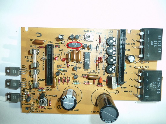
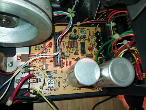
markings on the front amp panel (near the line/micro faders) state it's a double track capstan drive 708el. Lamp housing states it's a 708el capstan drive. Here's the board:
Posts: 7477
From: Manchester Uk
Registered: Aug 2012
posted September 17, 2017 01:41 PM
Yes, I think it's the same as my "black" model except just to add further confusion into the melting pot it is labelled as a double piste machine.
Two Track mono capstan driven machine basically.
Your board appears very very clean there Stuart and as we have discussed previously appears to be fully working with respect to the functions of the floating roller , the mask, lamp and LDR's so hopefully it won't need much to get it calibrated well.
If you run out of ideas Stuart and still are getting no joy with the wow issue, a main motor for these can be purchased fairly inexpensively to eliminate any possible brush problems.
The reading appears ok though as Phil says.
-------------------- "C'mon Baggy..Get with the beat"