|
Author
|
Topic: Bauer T10 problem
|
|
|
|
|
|
|
|
|
|
|
|
|
|
|
|
|
|
|
|
|
|
|
|
|
|
|
|
|
|
|
|
|
|
|
Andrew Woodcock
Film God
Posts: 7477
From: Manchester Uk
Registered: Aug 2012
|
 posted May 10, 2017 04:16 PM


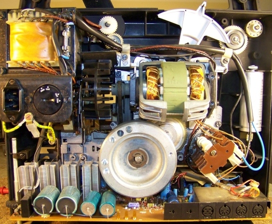
Just noticed the large capacitor for the motor also which is a dead giveaway that its an a.c. motor also.
David, if Barry gets nowhere with this tonight, (it's becoming late here already for a school night!😂), could you possibly confirm tomorrow on your model that the motor shaft itself moves in the same rotational direction in both forwards and reverse please?
Just the motor shaft itself please David.
This is typically how things are on these size of motors used in these applications, but there is a very slight possibility it could rotate in both directions depending on run and start winding configurations if a switch was fitted to it internally.
(Highly unlikely though and certainly doesn't appear to be this type)
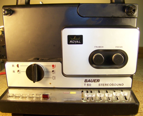
We very much first need to establish what enables this type of machine to switch from forwards to reverse direction from the actual main control knob. It is not clear from any of the photographs so far, whether the knob also moves a series of mechanical linkages like on the T610. This can only be seen from the front of the machine with the cover removed.
Even then, on a 525 /610 these linkages do not control the motor direction because it has a D.C. motor, but on this one, they may I'm guessing, through a series of gears. (Again unclear just from these photographs alone. The flywheel doesn't help either for seeing what happens to the main drive belt and beyond. It appears to go down to a worm gear I'd guess).
--------------------
"C'mon Baggy..Get with the beat"
| IP: Logged
|
|
|
|
|
|
|
|
|
|
Barry Fritz
Phenomenal Film Handler

Posts: 1061
From: Burnsville, MN, USA
Registered: Dec 2009
|
posted May 11, 2017 09:20 AM


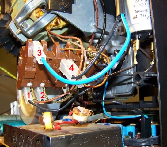
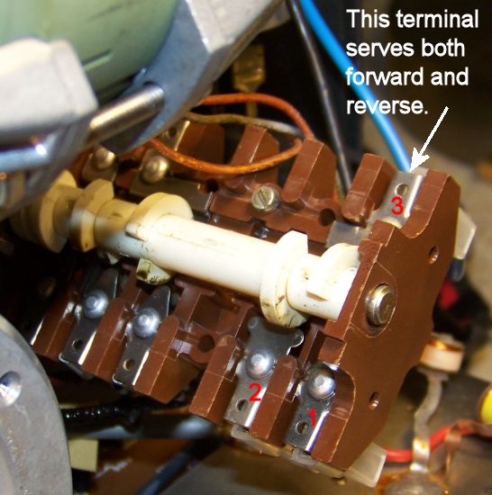
Hey Guys: Andrew, the motor has three wires. One green and two orangish. I did a bit of testing. I have determined that the terminal 1 is for Forward, and terminal 2 is for Reverse. Each terminal has a wire from the motor and a black wire running to the capacitor. Terminal three is double, and serves terminals 1 and 2. It has a blue wire that runs up to the transformer. Number 4 is a coupling that has an orange wire from the motor and a black wire that runs up to a terminal on the back of the dial where you select the voltaqe. Thus, I believe it is the power to the motor. Voltage readings for terminals are as follows:
Terminal 1: Off is 121.8V On is 200.7V
Terminal 2: Off is 121.8V On is 121.8V
I cannot figure out why the 200.7V reading is there.
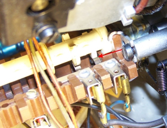
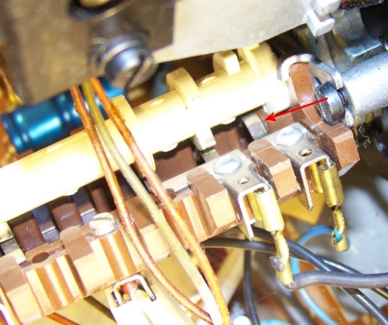
UPDATE: I think I found the problem. First off, when the cam turns down into the assembly, that disconnects the circuit. It pushes down a small metal tab that is the connector. Turning the cam up releases the little tab and it touches the terminal across from it. It seems to be working on the Forward terminal, but I can't see if the tab is actually touching. So, I took a jumper wire and fixed it to terminal three and touched the other end to terminal 1. Voila, motor spins nicely. Now I have to see if I can discover why the connection is faulty. The tab looks fine but it is supposed to touch the underside of the 1 terminal, and apparently it isn't. Some bending may be in order.
[ May 11, 2017, 12:37 PM: Message edited by: Barry Fritz ]
| IP: Logged
|
|
|
|
|
|
|


 UBBFriend: Email this page to someone!

![[Smile]](smile.gif)


 Printer-friendly view of this topic