This is topic Another Part for Edwin in forum 8mm Forum at 8mm Forum.
To visit this topic, use this URL:
https://8mmforum.film-tech.com/cgi-bin/ubb/ultimatebb.cgi?ubb=get_topic;f=1;t=009840
Posted by Paul Adsett (Member # 25) on March 17, 2015, 12:33 PM:
Here is another part for manufacturing consideration by Edwin's company.
It is the sound roller pressure arm of the GS1200. It serves to mount the rubber pressure roller which bears down on the sound capstan. It is made from hard plastic material, with a metal boss pressed in where it attaches to the solenoid shaft. The boss has two metric threads for inserting and tightening two grub (set) screws.
As manufactured by Elmo these arms have a common problem of cracking around the metal boss. This loosens the arm a bit, resulting in lowered pressure on the rubber capstan roller, and WOW distortion of the sound.
If Edwin were to remanufacture this part, there is no reason he could not beef up the wall thickness of the plastic around the boss to correct the cracking problem. Indeed he could sustantially taper that sharp corner where the profile of the hub intersects the arm feature, which would really stiffen up the arm considerably. No area of this part touches the film, and a superior part finish is not necessary, except the two little holes which locate the metal shaft of the rubber roller, which may have to be precision drilled.
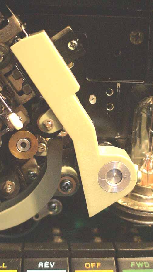
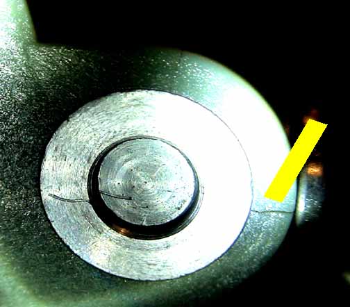
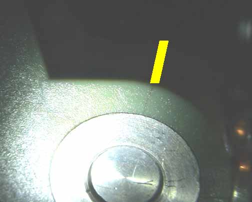
[ March 17, 2015, 01:56 PM: Message edited by: Paul Adsett ]
Posted by Andrew Woodcock (Member # 3260) on March 17, 2015, 06:01 PM:
Great post Paul and one surely to capture the attention of Edwin's team.
Like most of these plastic parts with inherent built in flaws surely just intended as a future spare parts healthy sales incentive at the time of designing,now Elmo are well and truly no longer as far as these machines are concerned, posts like yours from an expert engineering perspective, can only help ensure the future fitted parts never need to be purchased or re designed in the again.
I do hope all of the plastic guides for the GS1200 become available soon. It may reinvent my interest in these otherwise excellent machines for my optical prints, that is to say, if they did manufacture all of these guides and if I could secure one or two spare motors beforehand from somewhere.
[ March 17, 2015, 08:33 PM: Message edited by: Andrew Woodcock ]
Posted by Maurice Leakey (Member # 916) on March 18, 2015, 03:50 AM:
I believe at one time Wittners produced replacement Head Pressure Plates. I assume like at lot of things they no longer can supply.
As Paul said, if the little grub screws are over-tightened the green plastic cracks and correct pressure on the magnetic heads is lost.
Posted by Chris de Gruiter (Member # 4744) on March 18, 2015, 03:59 AM:
These five parts are on our project list. The three parts at the top of the machine show signs of wear and the two at the bottom are likely to crack.
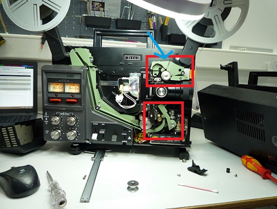
But I've one question about one the parts.
There is a screw hole (indicated with the blue arrow) at the top of that part, does anybody know where this is for? Because if it doesn't serve a purpose there no need to incorporate it in the new design.
Posted by Andrew Woodcock (Member # 3260) on March 18, 2015, 05:29 AM:
Chris, having never owned one of these projectors I cannot answer that, someone who does have one of these will be able to tell you of its function.
What I will say is, if there is a screw in the guide,then it will need to be replicated in the new guide as it WILL serve some purpose or other for certain.
Posted by Maurice Leakey (Member # 916) on March 18, 2015, 07:31 AM:
The Service Manual shows the hole but is quite silent on its function. No reference to it in words.
Posted by Steven J Kirk (Member # 1135) on March 18, 2015, 07:39 AM:
Excellent idea. This 'sound pressure lever', don't know the correct term, I would buy a couple of these. All the ones I have DO have tiny splits like Paul says.
The second guide needs the second roller addition to be the best version.
Posted by Andrew Woodcock (Member # 3260) on March 18, 2015, 07:41 AM:
Very peculiar that is Maurice??
All 5 of these parts will be extremely popular Steven I am sure though the best initial film feeding guide shoe that can be purchased for these is without doubt the Machined aluminium (I think) ones from Wittners or the likes.
Posted by Steven J Kirk (Member # 1135) on March 18, 2015, 08:02 AM:
Yes, the first position guide; there are metal versions from Wittner and FFR. They are slightly different. The Wittner ones I do have a pair in my main machines. They are steel and chrome-plated as far as I can tell. The FFR one has a V-shaped recess for film and may be aluminium. The Wittner is more like the original. Some also prefer the original plastic guide with a roller fitted at the back.
On the second guide I was fortunate to get my two guides changed to double roller and they work great and make logical sense considering how the film path goes. I think the ultimate second guide part would be metal, have the two rollers and flip up slightly with a satisfying click to enable removal of film easily.
[ March 18, 2015, 09:56 AM: Message edited by: Steven J Kirk ]
Posted by Andrew Woodcock (Member # 3260) on March 18, 2015, 08:09 AM:
Steven, put those ideas forward to Chris and Edwin, you may be onto a winner!
I think the guide would still need to be made from plastic for Edwin to manufacture at a price point that suits all, but may be able to incorporate the extra rollers also made by 3D tech to make the path "safer" from scratches.
The same may be necessary for the guide near the mag head which I know Dave Locke had to fit an extra roller before it was scratch free.
If these MKII versions of the guides had all of these modifications incorporated into their new design, that might well be the end of the scratch associated issues on these otherwise excellent machines. ![[Razz]](tongue.gif)
Posted by Chris de Gruiter (Member # 4744) on March 18, 2015, 08:40 AM:
Are there any pictures available with those double rollers you guys are talking about, because I'm not familiar with those.
Posted by Alexander Vandeputte (Member # 1803) on March 18, 2015, 08:53 AM:
Yes look in this thread.
http://8mmforum.film-tech.com/cgi-bin/ubb/ultimatebb.cgi?ubb=get_topic;f=1;t=001885#000010
Posted by Steven J Kirk (Member # 1135) on March 18, 2015, 09:48 AM:
This is the double roller mod:
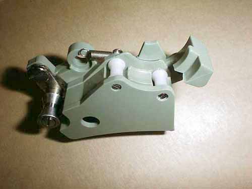
As you can see the guide is shaped as if it should always have had two rollers.
With the FFR guide:
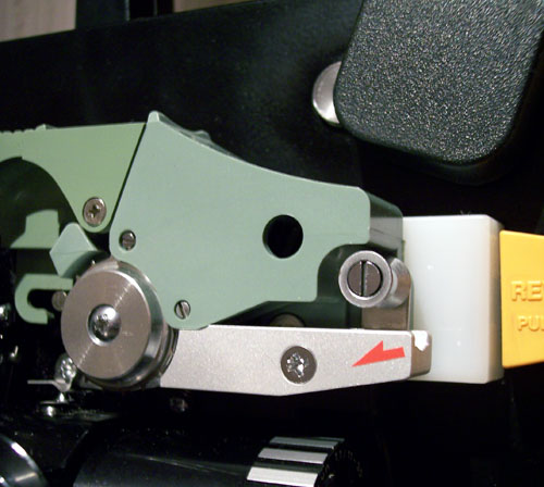
Posted by Paul Adsett (Member # 25) on March 18, 2015, 02:12 PM:
That modified guide with the two plastic rollers is definately the preferred design configuration for any new parts. I would love to get this onto my machines.
Posted by Andrew Woodcock (Member # 3260) on March 18, 2015, 02:16 PM:
It appears a very easy modification to carry out if you can get your hands on the two small rollers from an old donor ST1200.
Better still if Edwin can make the rollers! ![[Razz]](tongue.gif)
To me it would be better still if the middle section were missing altogether and a third roller was positioned in the middle of the other two so no stationary part of the guide comes into contact with the film as the passes through the top sprocket in a curve.
Posted by Paul Adsett (Member # 25) on March 18, 2015, 02:31 PM:
Will someone please explain to me why the metal feed guide does not scratch the film, whereas the plastic one does. I am assuming that the answer is that the plastic feed guide wears down so that the guide profile no longer is totally relieved from the picture area of the film. I think someone, perhaps Dave Locke, also put a roller on the sprocket end of the feed guide, which is probably better than even the metal version of this guide.
Posted by Paul Browning (Member # 2715) on March 18, 2015, 02:32 PM:
This is the mod on both my gs 1200's, I thought this was a mod that bill parson's had done?, perhaps not then, a good tweak by someone never the less.
Posted by Andrew Woodcock (Member # 3260) on March 18, 2015, 02:35 PM:
Perhaps Paul but my friend has used the metal shoe for many years and his films are perfect.
Yes it is due exactly to the reasons you say regarding wear to the plastic version.
Also Paul, see my latest post on Eumig 3000, I am sure the video will really interest you if you don't already have this on your discs.
[ March 19, 2015, 10:31 AM: Message edited by: Andrew Woodcock ]
Posted by Steven J Kirk (Member # 1135) on March 18, 2015, 02:41 PM:
To clarify, the problem on both the first and second guide parts is that wear can create a flattened surface that can touch the picture area.
Posted by Andrew Woodcock (Member # 3260) on March 18, 2015, 05:06 PM:
As said Steven clarifying Pauls suspicions, but thanks for cementing this ![[Razz]](tongue.gif)
Posted by Paul Browning (Member # 2715) on March 19, 2015, 04:27 PM:
Hi Chris, I now have some pictures of the lower guide, one used so you can see where the wear takes place on guide, and one with the modified guide with the roller in place. I have taken a measurement form the centre of the countersunk fixing hole to the centre of the roller fixing if you need that too. Let me know your email address please, as I have problems uploading pictures to the site still, I have asked a fellow member( Andrew Woodcock) who very kindly did this for me, but I'm not going to keep imposing on him to do this. So please let me know.
Posted by Andrew Woodcock (Member # 3260) on March 19, 2015, 05:42 PM:
Paul, its no trouble at all mate if you want one or two placing here. Just let me know mate, I'm up for another 30 minutes yet if you want it on for tomorrow morning?
Posted by Maurice Leakey (Member # 916) on March 20, 2015, 05:45 AM:
Going back to Chris' original question about the auto-thread lever and its hole, I have just look at a GS1200 and see that it is not a hole right through but just a round depression.
It certainly doesn't seem to be of any use, was it perhaps used in the mould for some reason?
Posted by Chris de Gruiter (Member # 4744) on March 20, 2015, 06:20 AM:
The 3 parts that show signs of wear of modeled and will be send to the printer shortly. I've included the extra roller and I hope to be able to give you guys more information about its resistance against wear in about 3/4 weeks.
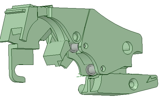
I'll keep you updated on the other parts of the Elmo GS1200
Posted by Andrew Woodcock (Member # 3260) on March 20, 2015, 06:39 AM:
Fabulous work there Chris!
Posted by Paul Adsett (Member # 25) on March 20, 2015, 06:39 AM:
Wonderful news! I would think just about every owner of the GS will want to buy this much improved design part. But can we also get the roller put into the part with the arrow? This would totally eliminate any wear issues associated with the top guides.
Posted by Andrew Woodcock (Member # 3260) on March 20, 2015, 06:45 AM:
I will be really interested to see the outcome in use in around a year or so Paul,with all of these new parts fitted to somebody's machine.
Hopefully with these 3 guides fitted and the one fitted near the head section with the modification that Dave Locke introduced by fitting an extra roller in the base of it....,
There will be such a thing as a failsafe GS1200 in the scratch department!
Now that really would be something!
I have the video of Dave showing his mod to the lower guide so I will try and capture a still of it and place it on here for Chris to view. That way,hopefully all the replicas made will be modified in the manner Dave did to make his machine completely scratch free I believe. ![[Smile]](smile.gif)
Ps the steel initial feed shoe is a trusted option Paul for the "arrow" guide. No roller fitted but does work flawlessly by all accounts.
Posted by Edwin van Eck (Member # 4690) on March 20, 2015, 07:37 AM:
As you can see, our engineers (one of these is Chris) can make quite complex parts using the 3D printing. If you have wishes for other parts, please let uw know!
We hope to bring these parts on the market soon!
Posted by Chris de Gruiter (Member # 4744) on March 20, 2015, 08:43 AM:
Paul, I've now also added a roller into the part with the arrow ![[Smile]](smile.gif) In about 3 or 4 weeks I'll have the first results.
In about 3 or 4 weeks I'll have the first results.
Posted by Steven J Kirk (Member # 1135) on March 20, 2015, 10:59 AM:
Wow... is all I can say.
And, it is going to be GREEN then?
Posted by Paul Adsett (Member # 25) on March 20, 2015, 07:56 PM:
That's fantastic news Chris! We are all looking forward to a totally scratch free GS1200, for the first time! ![[Smile]](smile.gif)
Incidentally Chris, as a semi retired engineer, I am curious to know what CAD software you use to generate your 3D models. All the work that I have done, designing aerospace systems, has been carried out with PTC Pro/Engineer. This is a parametric CAD softare which automatically regenerates the part or assembly drawing when any changes are made to the 3D model(and vice-versa). Very powerful software indeed.
Posted by Andrew Woodcock (Member # 3260) on March 20, 2015, 08:15 PM:
Good 21st Century Stuff indeed Paul! Please don't retire any time soon, the world is totally devoid of quality Engineers!!
Pass as much on Paul as you can before giving up the mantell!!
Posted by Paul Adsett (Member # 25) on March 20, 2015, 09:27 PM:
Computers have truly revolutionized mechanical design Andrew. It is now possible to 3D model complex parts and assemblies, fit and function check everything, before anything is made. Using what is called finite element analysis, it is also possible to subject the part or assembly model to all the thermal, static, and vibration forces that it will experience in use. Literally, the actual testing of the finished part is usually more or less a routine confirmation of the analyis already carried out. These days, if something fails in actual test, someone has screwed up!
The whole field of mechanical design and analysis is very exciting, so much so that I wish I were starting out again!
In that regard I envy Chris and Edwin working in the emerging world of 3D printing.
Posted by Paul Browning (Member # 2715) on March 21, 2015, 09:10 AM:
Just wondered Paul, could this software be used to test our MP'S before we elect them to Parliament?. I doubt any would pass it.
Posted by Andrew Woodcock (Member # 3260) on March 21, 2015, 09:29 AM:
Great explanation Paul to someone who has always been "on the tools" so to speak rather than the design end of things.
As you say though, exciting times ahead Paul. Just need to find a solution for the mag head cores now!
Going to strip a scrap one down next time I am off to see what may or may not be possible.
Posted by Chris de Gruiter (Member # 4744) on March 23, 2015, 03:10 AM:
Paul, we've tried different types of 3D software and personally Solidworks is my favorite. We found that free programs like Sketchup are just not good enough and very devious to work with.
Posted by Paul Adsett (Member # 25) on March 23, 2015, 10:03 AM:
Hi Chris, I have never used Solidworks but it is used by a lot of aerospace companies in the US, and has an excellent reputation.
All these 3D CAD systems are amazing at what they do and it is now hard to believe that it was all once done on a drawing board!
But in a way, this is exactly analagous to film animation. Walt Disney's masterpiece Snow White was of course all done with hand drawings on a drawing board, and today it is all done on a computer by a team of software artists.
Posted by Dominique De Bast (Member # 3798) on March 23, 2015, 11:32 AM:
The difference, in my point of vue, Paul is that Disney was the centre of his creations. In the case of cartoons made with computers, the conceptors of the softwares are big parts of the process.
Posted by Paul Browning (Member # 2715) on March 23, 2015, 01:20 PM:
Chris, I have sent you a new email regarding the lower guide details, with some new measurements for the roller position.
Posted by Chris de Gruiter (Member # 4744) on June 25, 2015, 09:31 AM:
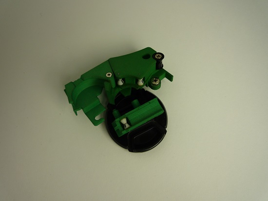
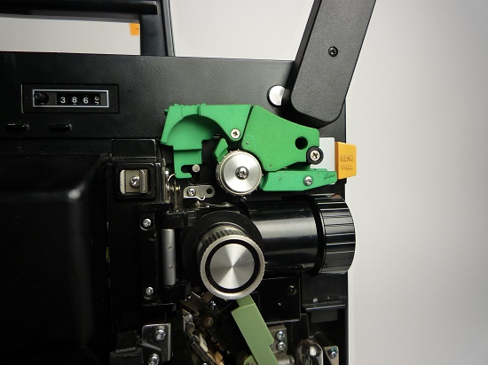
The first version of the film guide is done (green of course), as you can see we've included the 2 extra rollers. Our findings of these rollers are that the don't rotate and therefore can be left out. The problem is that we don't have the means to test these thoroughly. Do any of you guys have interest in these parts to test them for us?
Posted by Alexander Vandeputte (Member # 1803) on June 25, 2015, 10:56 AM:
I am in ! I'll gladly test this out. Sent you a PM
Posted by Edwin van Eck (Member # 4690) on July 08, 2015, 09:10 AM:
Hi Alexander,
The guide parts have been shipped to you. Eager to find out your findings!
Posted by Alexander Vandeputte (Member # 1803) on July 22, 2015, 03:14 PM:
I have finally found some time to briefly test the newly made film-guides for the Elmo GS1200 made by Edwin Van Eck and his team.
Fascinating in a way to receive brand new parts for a machine that has seen it’s last production run somewhere at the end of the eighties.
The input guide is a modified version including a roller where most of the wear usually occurs.
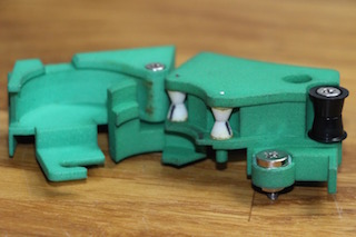
The upper guide is based on the version 1 Elmo as the roller is plastic and it does not trigger the microswitch found in later models.
The main attraction here, is the addition of a second roller, placed where usually a lot of ‘line inducing’ wear occurs.
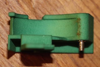
The loop former is identical to the original but without the tiny copper spring.
Installing the pieces was a breeze as everything fit perfectly. Loading the film through the input guide went flawless.
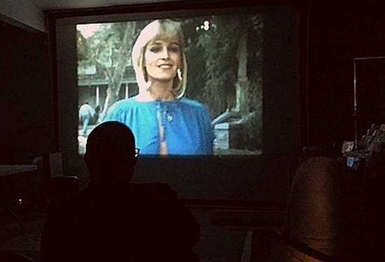
But as you can see on the pictures, the film makes contact with the loop former and that is where scratching occurs.
The culprit: the second roller is too retracted. If it was placed slightly more upwards, it would push the film further away and it would avoid scratching.
Conclusion: Edwin and his team are almost there ! I think it would be good to experiment with the placing of the second roller. And personally, I prefer the modified shape of the metal input guide from Wittners as it avoids any contact with the image surface of the film. I wonder if that part could be copied too…
In a couple of weeks I hope to run some more tests…
Posted by Andrew Woodcock (Member # 3260) on July 22, 2015, 03:38 PM:
Great informative post Alexander and one which hopefully will eventually pave the way for a scratch free future on any GS1200 with further modifications.
From what I have witnessed and spoken with others about it, I don't believe the precision machined steel Wittners input guide can be improved upon or would ever cause a problem.
The real need from all accounts is to replace the other green guides with improved ones that include rollers like these but in precisely the right place and of the exact right shape and diameter to keep that running film surface well and truly away from any stationary plastic!
Posted by Chris de Gruiter (Member # 4744) on September 07, 2015, 09:23 AM:
Alexander,
Thank you so much for your time and effort. We've incorporated your finding in the new designs.
The input guide now has the same shape as the one from Wittners does. And the position of the second roller is placed more upwards. Also the place were the film rubbed against the loop former is changed so that the film has a more gentle curve to follow.
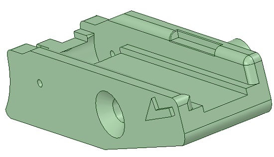
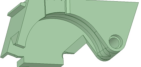
The new pieces will soon be printed and assembled. We hope that we can rely on you (Alexander) again to test the redesign for us. Please let us know if you're still interested in doing so. Your help is very much appreciated.
Posted by Paul Browning (Member # 2715) on September 07, 2015, 12:49 PM:
Hi Chris, Some good progress made on these guides. I have a more modified loop former guide, where your picture shows where the film has been in contact with part of this loop former guide. My guide has a roller here, to prevent this, I do have your email address would you like me to take a picture of this, as this may be a better alternative. Anything the film come's into contact with is liable to scratch or damage the film if its static( not moving) regardless of how polished or shiny it is. I would like to see rollers around the loop former too.
Posted by Alexander Vandeputte (Member # 1803) on September 07, 2015, 01:29 PM:
I think Paul is raising a valid point here. Adding a roller to the loop former, exactly where the wear occurs is an interesting option to explore. I have never seen that mod and am curious to see a picture of it.
To Chris: I will happily test your new designs. Only thing is: I am very busy at work and will only have enough time by the end of September. If that is no problem: bring them on I would say.
Posted by Chris de Gruiter (Member # 4744) on September 08, 2015, 04:21 AM:
To Paul, I would definitely like to see your version of the loop former. I'm very curious to see how you incorporated a roller there.
To Alexander, I think the end of September would be ideal for us because it takes some time to print and assembled the pieces.
Posted by Steven J Kirk (Member # 1135) on September 27, 2015, 03:55 PM:
Any updates on these guides?
Since the second guide with the two rollers - shown above - has no space for the micro-switch can someone confirm that the function of that is only the torque on reverse projection. This is what I remember. This new guide would be suitable for a later machine one would just lose the micro-switch and that function?
Posted by Tom Photiou (Member # 130) on September 27, 2015, 04:44 PM:
these 3D printers are going to be the life line of projectors and just about anything mechanical, it'l be parts to order for some lines of manufacturing. When i had the 24fps clutch wheels made 11 years ago now ![[Eek!]](eek.gif) the process was manic, a good original had to be copied and drawn by a machine with a laser, then the materials sourced and lathed to perfection, the cost back then was £600 for ten, thanks to this very forum all were sold,
the process was manic, a good original had to be copied and drawn by a machine with a laser, then the materials sourced and lathed to perfection, the cost back then was £600 for ten, thanks to this very forum all were sold,
What the van ek team are doing is nothing short of a miracle for this hobby. If only there were 3D printers 10 years ago
http://8mmforum.film-tech.com/cgi-bin/ubb/ultimatebb.cgi?ubb=get_topic;f=1;t=000333 ![[Big Grin]](biggrin.gif)
![[Wink]](wink.gif)
Posted by Mathew James (Member # 4581) on September 27, 2015, 05:06 PM:
I agree.
3D printing is amazing!
One question, since people have stumbled on this a few times already....
Can any colour dyes be added to the main plastic before/while printing? In otherwords, Can one print any part in any colour they want?
Cheers,
Matt
Posted by Andrew Woodcock (Member # 3260) on September 27, 2015, 05:58 PM:
I do not know technically how it is done Mathew, but for sure the 3D stuff seems to be able to be manufactured in any colour.
No doubt Edwin or Chris will fill us in on this. ![[Smile]](smile.gif)
Posted by Brian Fretwell (Member # 4302) on September 27, 2015, 06:16 PM:
From what I have seen of theses printers they can print with any colour raw plastic that is available. You buy it in a roll, like thick wire, which feeds into the 3D print head extruder.
Here's an example :- http://www.maplin.co.uk/p/up-plus-2-3d-printer-a25lt
Posted by Edwin van Eck (Member # 4690) on December 21, 2015, 10:14 AM:
Hello all,
I have some good news. The three improved films guides for the Elmo GS-1200 (can these also be used for other Elmo's??) are ready!!!!
Alexander has tested the first version. Based on that we have made the final improvements and these are ready now. Currently being busy with adding these to the shop and spare part finder http://www.van-eck.net/itable.php?lang=nl&size=0&cat=film&merk=52&type=GS%201200
I hope tomorrow these are online. I really think these guides are better then the original ones and do not scratch the film.
Posted by Andrew Woodcock (Member # 3260) on December 21, 2015, 11:48 AM:
It is impossible for them to be any worse than the originals Edwin. No doubt a big improvement!
Posted by Edwin van Eck (Member # 4690) on December 22, 2015, 01:42 AM:
The film guides for the Elmo GS1200 series are now ready:
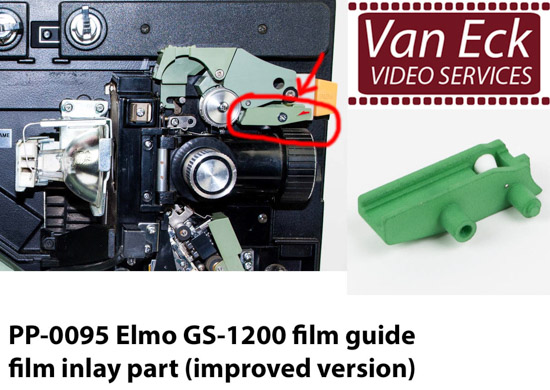
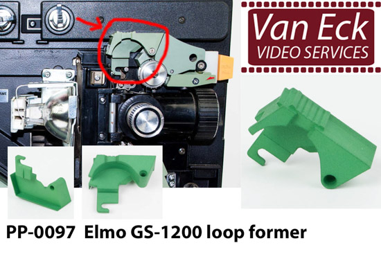
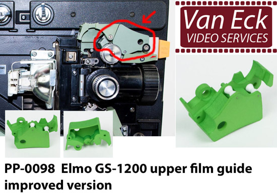
For more information and ordering, see the Van Eck spare part finder for Elmo GS1200:
http://van-eck.net/itable.php?lang=nl&size=0&cat=film&merk=52&type=GS%201200%20M-O%20Stereo
I have one set now on stock. Additional orders will take 1-2 weeks to fabricate.
Thank you all for your input, especially Alexander for testing.
I am confident this new set of guides will reduce scratching many films played on the nice Elmo GS-1200 machines.
Posted by Andrew Woodcock (Member # 3260) on December 22, 2015, 02:03 AM:
let's hope so, as in many cases now,you get but one solitary chance with our films nowadays.
In many cases, once ruined, there is little chance of finding another.
Criminal really how this class of machine was ever capable by original design, of some of the damage it did to their owners prints!
I have received prints that have been projected only a handful of times through these by their previous owners, and still they were damaged quite badly. ![[Confused]](confused.gif)
Posted by Graham Ritchie (Member # 559) on December 22, 2015, 02:44 AM:
That's fantastic Edwin ![[Cool]](cool.gif) will be in touch after the New Year
will be in touch after the New Year ![[Smile]](smile.gif)
Posted by Andrew Woodcock (Member # 3260) on December 22, 2015, 03:25 AM:
You and every other owner of these no doubt.
It's also funny how everyone who has one claims theirs doesn't scratch until you see their prints and see Edwins order book for these, no doubt now.
I am certain these will be a best seller for you Edwin
![[Wink]](wink.gif)
[ December 22, 2015, 05:28 AM: Message edited by: Andrew Woodcock ]
Posted by Edwin van Eck (Member # 4690) on December 22, 2015, 09:05 AM:
I think these guides work on these projectors:
- Elmo ST-1200
- Elmo GS-1200
- Elmo ST-160
- Elmo ST-180
- Elmo ST-600
- Elmo ST-800
- Elmo TRV-R8
- Elmo TRV-S8
Please correct me if I am wrong!
Posted by Andrew Woodcock (Member # 3260) on December 22, 2015, 09:08 AM:
The input guide is certainly different on a GS1200 to the one on a ST1200.
Posted by Paul Browning (Member # 2715) on December 22, 2015, 09:52 AM:
Still no roller on the loop former Edwin?, surely in your tests this has shown to be a high risk area of this part as the film is in contact with this leading edge, other than this, they look great very well done.
Posted by Edwin van Eck (Member # 4690) on December 22, 2015, 09:55 AM:
The roller is on the part next to the loop former (PP-0098), This roller is placed at the outer edge, preventing to touch the loop former.
Posted by Paul Browning (Member # 2715) on December 22, 2015, 10:24 AM:
Great Edwin, I have one gs that does not have these mods, especially the new parts with rollers and if this allows the film to miss this area, its a long way to protecting our hard to find prints from getting trashed, a fit and forget part. ![[Smile]](smile.gif)
Visit www.film-tech.com for free equipment manual downloads. Copyright 2003-2019 Film-Tech Cinema Systems LLC

UBB.classicTM
6.3.1.2


![[Razz]](tongue.gif)

![[Razz]](tongue.gif)
![[Razz]](tongue.gif)

![[Smile]](smile.gif)
![[Smile]](smile.gif) In about 3 or 4 weeks I'll have the first results.
In about 3 or 4 weeks I'll have the first results.
![[Smile]](smile.gif)


![[Eek!]](eek.gif) the process was manic, a good original had to be copied and drawn by a machine with a laser, then the materials sourced and lathed to perfection, the cost back then was £600 for ten, thanks to this very forum all were sold,
the process was manic, a good original had to be copied and drawn by a machine with a laser, then the materials sourced and lathed to perfection, the cost back then was £600 for ten, thanks to this very forum all were sold, ![[Big Grin]](biggrin.gif)
![[Wink]](wink.gif)
![[Smile]](smile.gif)


![[Confused]](confused.gif)
![[Cool]](cool.gif) will be in touch after the New Year
will be in touch after the New Year ![[Smile]](smile.gif)
![[Wink]](wink.gif)
![[Smile]](smile.gif)