|
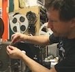
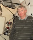
Author
|
Topic: Procedure for installing 2-blade shutter on Elmo GS1200
|
Paul Adsett
Film God
Posts: 5003
From: USA
Registered: Jun 2003
|
 posted February 09, 2013 02:20 PM


Here is Part 1 of the procedure to install a 2-bladed shutter on the Elmo GS1200. Reference is made to the appropriate figures of the GS1200 Service Manual, which can be downloaded from this forum.
Part 1 is the disassembly process.
PROCEDURE FOR INSTALLATION OF 2-BLADE SHUTTER
. ON THE ELMO GS1200
All references are to the appropriate pages and figures of the Elmo GS1200 service manual.
Important : use of magnetic tools is essential to avoid loss of screws, washers, and lock washers. Use brand new tools you only get one chance to loosen most of the Elmo screws before they will round over and you will never get them loose.
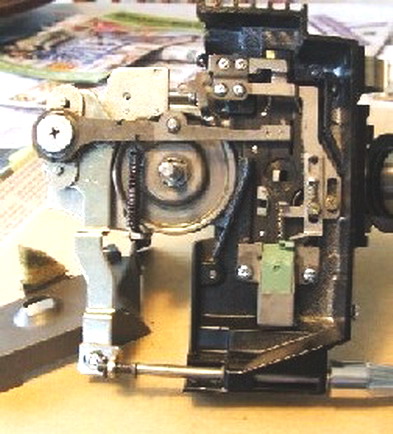
REMOVE THE LENS
Part 1 Disassembly/tear down
Step 1 Remove the front cover
Manual Fig 1.
Unscrew the little pin , item 2 , and pull the cover slightly forward from the rear pin to remove it.
Step 2 Remove the rear cover
Manual fig 2
Unscrew the two screws item 2, pull the cover away just far enough to reach in and disconnect the speaker connector item 3.
Step 3 Remove Amplifier Cover
Manual fig 3
Pull off all the round knobs, 2,3,4 and all the swich covers 5,6,7,8
The amplifier cover is held on by 3 screws. The first is item 8 at the front bottom of the cover. The other two screws are accessed from the backside of the projector at the extreme top right corner, and bottom right corner of the chassis wall. The top right screw will want to fly over and attach itself to the take-up motor , so be careful. Remove all 3 screws and pull off the amplifier cover from the front side, while disconnecting the meter connector item 9
Step 4 Remove the big green plastic film guide
Manual Fig 38. Unscrew the screws item 2, and remove the film guide
Step 5 Remove the Top Green auto-threading guides
Manual Fig 13. Remove 19,18 . Remove 1 and 6. . Remove the 5, 2 and 3 being careful not to lose the little spring item 3.
If the machine is a version 3, it will be fitted with a little microswich activated by the front roller. You will have to unsolder the 2 wires to the microswitch.
Step 5 Remove the lamp and wire shroud.
Manual fig 39
Remove the lamp housing cover a. Remove the bulb 3,. Remove the two screws, item 2, holding the lamp holder and swingthe lamp holder away from the back of the gate area.
Unscrew the single screw holding the black wire shroud, located below the lamp, and remove the shroud.
Unbolt the 2 screws that hold the little bulb that shines down by the loop restore lever, and swing the lamp and cable out of the way.
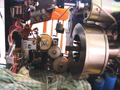
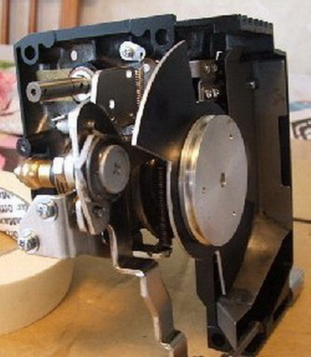
STEP 6 Removal of gears and switches
Manual fig 4.
1. Remove the flywheel 2,3,4. There is probably a grounding spring on the end of the flywheel shaft, attached to the PC board via a metal bracket and a screw and lockwasher. This is not shown in my manual, but it has to be removed before removing the flywheel.
2. Remove the swinging arm 6, which is attached with two screws 5.
3. Remove the gear assembly 17,18,19,20,21,22 as one piece (no need to disassemble), by removing the two screws holding the plate to the chassis.
4. Remove the gear assembly 9,10
5. Remove the gear assembly 7,8
6. Push off the snap ring 11 very carefully dont lose it!
7. Very carefully pull off the gear 12. It is keyed to the shaft by a tiny pin 13. Make sure not to lose that pin into the innards of the projector.
8. Remove the gear assembly 10, by unscrewing the 2 bolts 9
9. Remove the 2 bolts 14 holding the microswitch 16, and lift out the microswitch no need to unsolder the wires.
10. Remove the reed switch 24, by unscrewing the bolt 23. No need to unsolder the reed swich, just lift up from behind the drive shaft so that it is clear of other parts.
11. Unsolder the two wires from the solenoid making sure that you note the correct color scheme to hook back up.
12. Remove the main drive belt 40. It can be carefully pried off the end of the motor shaft pulley.
13. Remove the 28,29, 30,31,32 from the lower sprocket shaft no need to pull out the sprocket and shaft.
14. The main mechanism block lifts off from the front side of the machine. You have to remove the four screws 39, and then you must carefully and slowly pull the mechanism out, with microswitch and reed switch coming with it. Avoid hitting the plastic gears on anything.
.
--------------------
The best of all worlds- 8mm, super 8mm, 9.5mm, and HD Digital Projection,
Elmo GS1200 f1.0 2-blade
Eumig S938 Stereo f1.0 Ektar
Panasonic PT-AE4000U digital pj
| IP: Logged
|
|
|
|
|
|
|
|
|
|
|
|
|


 UBBFriend: Email this page to someone!


![[Eek!]](eek.gif)


 Printer-friendly view of this topic