8mm Forum


my profile | my password | search | faq | register | forum home
  next oldest topic   next newest topic
» 8mm Forum   » 8mm Forum   » Eumig 824 Audio Line Out

 - UBBFriend: Email this page to someone!    
Author Topic: Eumig 824 Audio Line Out
Daryl Lannert
Junior
Posts: 2
From: Gurnee IL
Registered: Jan 2009


 - posted August 04, 2009 10:41 AM      Profile for Daryl Lannert   Email Daryl Lannert   Send New Private Message       Edit/Delete Post 
Hello
I have a Eumig 824. I am trying to utilize the line out on the projector into my Camera for audio capture. I am not interested in the video quality as I am using a Eumig 610 to do a 3 FPS capture for the video. I have been unable to receive a signal from the 824. Does anyone know what the problem might be? Thank you in advance.

Daryl Lannert

--------------------
"What the hell was that?!"
Mars Attacks

 |  IP: Logged

Martin Jones
Phenomenal Film Handler

Posts: 1269
From: Thetford , Norfolk,England
Registered: May 2008


 - posted August 04, 2009 01:00 PM      Profile for Martin Jones     Send New Private Message       Edit/Delete Post 
There is an anomaly here.
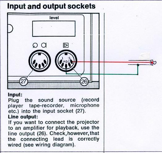
The instruction manual, page 9, says that for Line Output you should use socket (26), the one nearest the front of the machine, which is a 5 pin socket. This IS the correct socket.

The Specification, page 27, says to use pins 2 & 3. However, the Schematic on page 25 shows this socket as a 3 pin socket with Line Out connected to pins 1 (Ground) and 3.

I suggest that you adopt the following procedure. Use the CENTRAL pin as the GROUND of your output (this is standard) and then try each of the other pins in turn as the "live" signal. One of them will work. Line Out is only available on Playback, not on Record.

Martin

--------------------
Retired TV Service Engineer
Ongoing interest in Telecine....

 |  IP: Logged

Daryl Lannert
Junior
Posts: 2
From: Gurnee IL
Registered: Jan 2009


 - posted August 17, 2009 10:26 AM      Profile for Daryl Lannert   Email Daryl Lannert   Send New Private Message       Edit/Delete Post 
Thank you Martin for replying.
I apologize for my ignorance as I am confused with your procedure. Are you suggesting I use a multi meter to check the signal of the center pin on the projector? If this is correct how would I then attach the cable to that pin? Thank you for your patience.

--------------------
"What the hell was that?!"
Mars Attacks

 |  IP: Logged

Martin Jones
Phenomenal Film Handler

Posts: 1269
From: Thetford , Norfolk,England
Registered: May 2008


 - posted August 17, 2009 12:25 PM      Profile for Martin Jones     Send New Private Message       Edit/Delete Post 
Daryl,
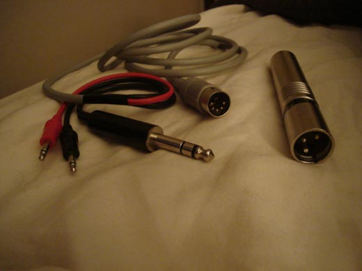
The line-out socket (which is the one neaest the front of the projector)has 5 pins. It's what's known as a 5-pin DIN socket; the "DIN" designation is a European one which was never accepted as a manufacturing standard on your side of the pond.
If you have not already got one, the matching plug is, I believe, available from Radio Shack.
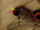
Now, the center pin is "signal Ground". On of the other four pins will be the one you require as the "signal OUT". So to obtain your "line-out" signal the center pin will be the one that connects to the "input ground" of your camera, and you will have to find by trial and error which of the other four is the one you want.
If you are not sure what you are doing, you would be advised to contact a local audio or electronics hobbyist. There is a strong possibility that the projector "line-out" signal may be too high for your camera input (it wouldn't physically do damage!) and that aspect would then need to be addressed.
Martin

--------------------
Retired TV Service Engineer
Ongoing interest in Telecine....

 |  IP: Logged

Dino Everette
Phenomenal Film Handler

Posts: 1535
From: Long Beach, CA USA
Registered: Dec 2008


 - posted August 19, 2009 12:54 AM      Profile for Dino Everette     Send New Private Message       Edit/Delete Post 
Thought maybe a visual might help you out with this one.. Here is an adaptor I use for the Eumig 5 pin out....
1) - The adaptor goes from the Eumig to a 1/4 inch jack
2) - 1/4 inch goes into another adaptor for XLR in on camera....

Hope that helps put Martin's explanation into perspective.

 -

--------------------
"You're too Far Out Miss Lawrence"

 |  IP: Logged

Martin Jones
Phenomenal Film Handler

Posts: 1269
From: Thetford , Norfolk,England
Registered: May 2008


 - posted August 19, 2009 02:49 AM      Profile for Martin Jones     Send New Private Message       Edit/Delete Post 
Thank you Dino, now all Daryl needs is to know which pins on the plug are connected to the 1/4 inch jack... are you able to help there?
Martin

--------------------
Retired TV Service Engineer
Ongoing interest in Telecine....

 |  IP: Logged

Dino Everette
Phenomenal Film Handler

Posts: 1535
From: Long Beach, CA USA
Registered: Dec 2008


 - posted August 20, 2009 12:20 AM      Profile for Dino Everette     Send New Private Message       Edit/Delete Post 
Oops my bad

Maybe this will help...The red and yellow lines point to the 2 wires that go to the top two pins on the 1/4 inch plug, plus the black/bottom one will go to the back pin on the 1/4 inch plug

 -

--------------------
"You're too Far Out Miss Lawrence"

 |  IP: Logged

Martin Jones
Phenomenal Film Handler

Posts: 1269
From: Thetford , Norfolk,England
Registered: May 2008


 - posted August 20, 2009 04:37 AM      Profile for Martin Jones     Send New Private Message       Edit/Delete Post 
Daryl,
This is specifically for the 824 which has Mono output. (For machines with Stereo the other channel comes from pin 5. Notice that the 5 pin socket has 5 pins spaced over 180 degrees; the plug must be the same (there is a different one spaced over 270 degrees).
If you cannot get a 5 pin plug, a 3 pin will fit OK; again spaced over 180 degrees.

 -

Martin

[ August 20, 2009, 09:44 AM: Message edited by: Martin Jones ]

--------------------
Retired TV Service Engineer
Ongoing interest in Telecine....

 |  IP: Logged

Grant Bennett
Junior
Posts: 4
From: London, UK
Registered: Aug 2014


 - posted August 28, 2014 07:45 PM      Profile for Grant Bennett   Author's Homepage   Email Grant Bennett   Send New Private Message       Edit/Delete Post 
Hello Forum;
I'm having a cable made up at the moment and my engineer has the following question about the post from Martin Jones. Belowis his question

My only concern is that Martin Jones appears to have shown the pin numbers on the DIN plug incorrectly, so the wires that he added are pointing to pins 1 and 2 (and 4 for stereo devices) in the DIN socket, but he has numbered these as 3 and 2 (and 5 for stereo devices). Hence, the plug could be wired either way around! Would you be able to clarify this with him please via the forum? (Sorry to be a pain!)

I look forward to an answer
Thanks
Grant

 |  IP: Logged

Maurice Leakey
Film God

Posts: 5895
From: Bristol. United Kingdom
Registered: Oct 2007


 - posted August 29, 2014 06:29 AM      Profile for Maurice Leakey   Email Maurice Leakey   Send New Private Message       Edit/Delete Post 
This should help.
http://www.electronics2000.co.uk/pin-out/dincon.php

--------------------
Maurice

 |  IP: Logged

Grant Bennett
Junior
Posts: 4
From: London, UK
Registered: Aug 2014


 - posted September 05, 2014 01:11 PM      Profile for Grant Bennett   Author's Homepage   Email Grant Bennett   Send New Private Message       Edit/Delete Post 
Many thanks. In the end I purchased a manual online and from the wiring diagram had a cable made up. This part of my problem is solved.
Now I seem to have a loud hum from the audio circuits. The hum is only present with the projector running forward light/sound on, reverse with light on is ok.

Is it usual for this hum or is it a component failing? I had the hum before when I was taking audio from the speaker connection but though it was because I was using the wrong audio out.

Any comments would be much appreciated.
Regards
Grant Bennett

 |  IP: Logged

Paul Adsett
Film God

Posts: 5003
From: USA
Registered: Jun 2003


 - posted September 05, 2014 11:25 PM      Profile for Paul Adsett     Send New Private Message       Edit/Delete Post 
There is a hum bucking coil mounted on a copper strip right underneath the sound head. Hum level can be minimized, but not eliminated, by moving the position of the coil by bending the copper strip slightly. Turn the projector on and set to forward run with light on and sound level set high, then move the hum bucking coil to minimixe hum level.
Additional hum reduction can be achieved by feeding the AUX output from the projector into a graphic equalizer, and 'notch' the filter settings on the equalizer at the hum frequency.

--------------------
The best of all worlds- 8mm, super 8mm, 9.5mm, and HD Digital Projection,
Elmo GS1200 f1.0 2-blade
Eumig S938 Stereo f1.0 Ektar
Panasonic PT-AE4000U digital pj

 |  IP: Logged

Grant Bennett
Junior
Posts: 4
From: London, UK
Registered: Aug 2014


 - posted September 06, 2014 04:48 PM      Profile for Grant Bennett   Author's Homepage   Email Grant Bennett   Send New Private Message       Edit/Delete Post 
Will try, Thanks Paul

 |  IP: Logged


All times are Central  
   Close Topic    Move Topic    Delete Topic    next oldest topic   next newest topic
 - Printer-friendly view of this topic
Hop To:

Visit www.film-tech.com for free equipment manual downloads. Copyright 2003-2019 Film-Tech Cinema Systems LLC

Powered by Infopop Corporation
UBB.classicTM 6.3.1.2